Table of Contents
- What more power actually buys you
- The legal framework: what is actually allowed in Austria
- The normal case: 400 watts
- High Power: 1 kW on application
- The bands in detail
- Spurious emissions, dummy load, CE
- Tube or LDMOS?
- Tube amplifiers
- LDMOS amplifiers
- The specifications that matter
- Drive, ALC and keying — where it gets expensive
- Drive level
- The ALC loop
- The keying line — the most common expensive mistake
- Hot switching and sequencing
- The antenna tuner in the right place
- Staying clean: two-tone test, splatter, harmonics
- Cooling and power supply
- Safety: high voltage, RF and exposure
- High voltage
- RF burns and RF in the shack
- RF exposure
- Grounding, bonding and lightning protection
- Commissioning, step by step
- Market overview 2026
- HF, solid state (LDMOS)
- HF, tube
- VHF/UHF
- Used-buying checklist
- The most common mistakes at a glance
- Sources and further reading
- Related articles on oeradio.at
- Image credits
- Transparency Notice
An amplifier is the most expensive box in the shack that contributes the least to making contacts — and yet almost everyone wants one eventually. This article works through what an amplifier really buys you, what the law in Austria actually says, how tubes and LDMOS differ in practice, how to set up drive, ALC, cooling and grounding, and how to spot a decent used unit.
What more power actually buys you
The most important number first, because it frames the whole discussion: power works logarithmically. On HF, one S-unit is defined as 6 dB — four times the power.
- 100 W → 400 W = 6 dB = exactly one S-unit
- 100 W → 1000 W = 10 dB = roughly 1.7 S-units
- 5 W (QRP) → 100 W = 13 dB = a bit over two S-units
Going from 100 to 1000 watts multiplies your power by ten and buys you just under two S-units. For comparison: swapping a vertical for a three-element Yagi gains about the same — in both directions, so on receive too, and without an electricity bill. Hence the old rule still holds: a euro spent on the antenna beats the same euro spent on the amplifier. If there is still headroom in your vertical, your EFHW or a directional antenna, start there.
That said, there are situations where an amplifier is the only answer:
- Pile-ups in contests and on DXpeditions — what counts is not absolute field strength but the margin over everyone else calling
- EME and meteor scatter — physically impossible without high power
- Compromise antennas — a magnetic loop or stealth antenna costs dBs that power can partly replace
- Low bands — 160 m and 80 m forgive very little, especially in summer
And there is one situation where an amplifier helps not at all: when you cannot hear the other station. Power does not improve your receiver. If you sit in a noise floor, the money is better spent on receive antennas and on hunting down the noise in your own house.
The legal framework: what is actually allowed in Austria
One misunderstanding is remarkably persistent: "a CEPT licence means 1 kW." It does not. What governs is the Frequenznutzungsverordnung 2013 (Federal Law Gazette BGBl. II No. 63/2014), Annex 4, as amended by the 2023 amendment BGBl. II No. 61/2023, in force since 13 March 2023.
The normal case: 400 watts
For holders of licence class 1, the regular ceiling on the HF bands is 400 W PEP. That is the power almost every Austrian station legally runs — and a 600-watt amplifier covers it with room to spare.
For licence classes 3 and 4, the limit is 100 W. More importantly in practice: in those classes, Annex 4 permits only unmodified commercial transmitting equipment. An external amplifier — let alone a homebrew one — is therefore effectively out of the question for class 3 and 4. Anyone wanting to move up takes the class 1 exam first; our licence class comparison lays out what each class is good for.
High Power: 1 kW on application
Since the 2023 amendment, the "High Power" level of 1000 W PEP can be applied for. The conditions, according to the Fernmeldebüro (the Austrian telecoms authority):
- licence class 1 only
- only on the HF bands 80 m, 40 m, 20 m, 17 m, 15 m, 12 m and 10 m
- the prerequisite is "at least one year of interference-free operation at power level B for the authorised location" — an existing power level C authorisation waives the waiting period
- application via the RAT system; High Power operation is prohibited until approval is granted
- the authorisation is tied to the location and carries a fee (on the order of 6.5 euros per month)
The "interference-free operation" clause is not a formality: if you have been in the neighbours' television for years, you will not get a power increase. That is a good reason to do the EMC homework before buying an amplifier rather than after.
The bands in detail
| Band | Max. power, class 1 | High Power possible? |
|---|---|---|
| 160 m (1810–1850 kHz) | 200 W | no |
| 160 m (1850–2000 kHz) | 100 W | no |
| 80 m | 400 W | yes |
| 60 m (5351.5–5366.5 kHz) | 15 W EIRP | no |
| 40 m | 400 W | yes |
| 30 m | 200 W | no (WARC) |
| 20 / 17 / 15 / 12 / 10 m | 400 W | yes |
| 6 m (50–52 MHz) | 200 W | no |
| 6 m (52–54 MHz) | 100 W | no |
| 2 m and 70 cm | up to 1 kW — but only EME and meteor scatter with Yagis of at least 15 dBd | special case |
| 23 cm | 10 W (GNSS protection) | no |
| 13 cm and above | 200 W | no |
On the WARC bands (30, 17, 12 m) the IARU agreement that no contests are run there applies as well — along with the good manners of not overdoing the power. For the heavily trimmed 23 cm band, see our microwave article.
Spurious emissions, dummy load, CE
Three provisions of the Austrian Amateurfunkverordnung (AFV) bear directly on amplifier operation:
- § 17 — unwanted emissions must be kept "to the lowest possible level"; between 50 and 1000 MHz a suppression of at least 60 dB relative to peak power applies. Without an effective harmonic filter behind the amplifier that is unachievable.
- § 14 — transmitter tuning requires tuning without unnecessary radiation — in practice: into a dummy load. For tube amplifiers with TUNE and LOAD that is not a recommendation but a legal requirement.
- § 13 — monitoring instruments requires suitable current and voltage meters. For an amplifier that means plate current, plate voltage, forward and reflected power must all be readable.
On CE marking: commercially bought amplifiers require CE marking under the Radio Equipment Directive RED 2014/53/EU and the EMC Directive. Homebrew equipment and kits built by and for radio amateurs are explicitly excluded under Art. 1(2)(c) RED as long as they are not made available on the market. Building your own is therefore permitted — which does not exempt you from the limits in § 17 AFV.
Tube or LDMOS?
The argument feels as old as the hobby, but technically it is fairly settled by now — with a few exceptions.
Tube amplifiers
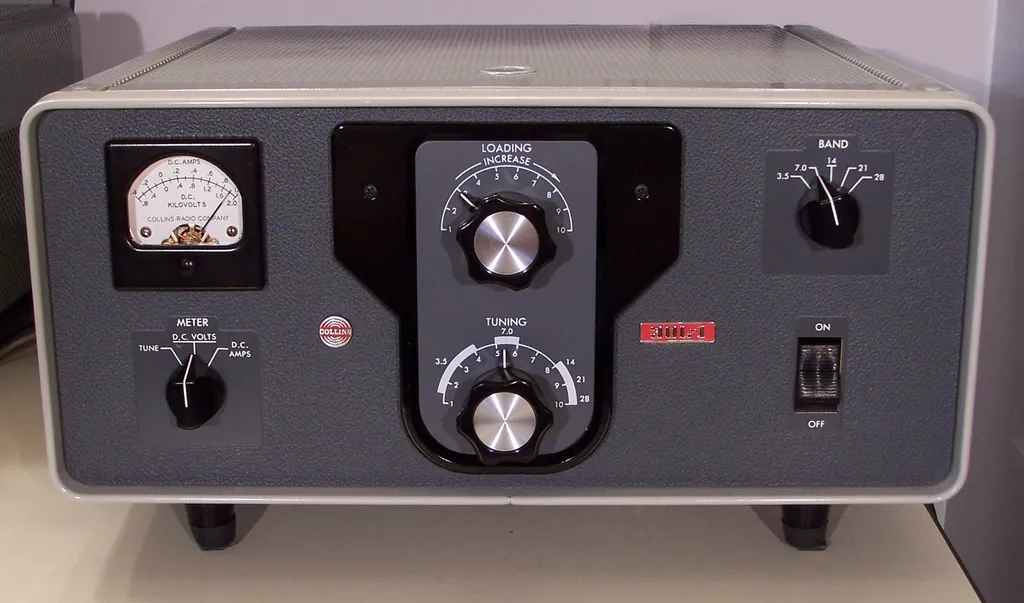
Usually grounded-grid triodes (3-500Z, 3CX1500A7) or tetrodes (GU-74B, 4CX800). The output network is a tunable pi filter — hence TUNE and LOAD, hence the manual band change.
- Forgiving of mismatch. A 3:1 SWR costs a tube some efficiency; it kills an LDMOS module.
- The pi network attenuates harmonics by design — a structural advantage where § 17 is concerned.
- Repairable. Change the tube, change a capacitor, carry on.
- But: 2000 to 4000 volts on the plate, 20 to 40 kilograms, warm-up time — and tube supply has become a problem. Russian types such as the GU-74B have been hard to source through regular channels since 2022, and prices for new American classics have risen sharply.
LDMOS amplifiers
Today's standard. One or two power transistors — usually BLF188XR or MRF1K50 — running on 50 to 65 volts, broadband, with switched low-pass filters per band.
- No tuning. Band changes in milliseconds, often automatically from the transceiver's band data. Practically mandatory for SO2R and serious contesting.
- No high voltage in the dangerous sense — 50 V is unpleasant, not lethal.
- Compact and light, some models under 15 kg, a few even portable.
- But: extremely sensitive to mismatch and overdrive. Without working protection circuitry a module dies in milliseconds — and a BLF188XR is a three-figure part.
| Tube | LDMOS | |
|---|---|---|
| Band change | manual (TUNE/LOAD) | automatic, instant |
| Operating voltage | 2–4 kV | 50–65 V |
| Efficiency | approx. 55–65 % | approx. 55–70 % |
| Behaviour at SWR > 2:1 | forgiving | must shut down or it dies |
| Harmonic suppression | inherent via pi network | via switched low-pass filters |
| Weight | 20–40 kg | 10–20 kg |
| Readiness | 1–3 min warm-up | instant |
| Repair | quite feasible | module replacement, expensive |
| Spares | tube sourcing difficult | readily available |
The specifications that matter
Drive power and gain. Typical figures are 12 to 14 dB of gain. A 1.3 kW LDMOS amplifier therefore needs roughly 40 to 60 watts of drive; a 1 kW tube amplifier needs about the same. If you run a QRP transceiver such as the IC-705 (10 W), you need either a high-gain amplifier or a two-stage arrangement — feeding 10 W into a kilowatt amplifier yields a third of rated output at best.
Intermodulation (IMD3). The decisive quality figure, and the only one the rest of the band notices. Good amateur amplifiers sit at −30 to −35 dBc for third-order products. Cheap unfiltered CB-style "burners" are orders of magnitude worse and produce a signal that splatters more than 20 kHz wide.
Duty cycle. The most consistently underestimated parameter:
| Mode | Average power | On a 1 kW amplifier |
|---|---|---|
| SSB (voice) | approx. 20–25 % | full power is fine |
| CW | approx. 40–50 % | full power, fan working |
| RTTY, FT8, FT4, PSK | 100 % | back off to roughly 500 W |
| FM (repeater, simplex) | 100 % | back off as well |
The rule of thumb for digital modes: half the rated power, full service life. Most manufacturers specify continuous-carrier operation at 50 percent of the SSB rating anyway. An FT8 transmission is 12.6 seconds of constant carrier — thermally an entirely different animal from an SSB QSO.
Drive, ALC and keying — where it gets expensive
Most amplifier damage does not come from overload in service but from incorrect wiring between transceiver and amplifier.
Drive level
The principle: you control the amplifier with the transceiver's output power, not with the ALC. Set the transceiver so that the amplifier reaches its rated output — and not one watt more. Overdriving barely raises output power but wrecks intermodulation performance.
The ALC loop
The ALC line feeds a negative voltage from the amplifier back to the transceiver, which reduces its output. It is an emergency brake, not an operating mode: the loop needs time, and during that time the overshoot has already reached the amplifier input — a well-known problem with the fast level steps of digital modes. If you constantly run the ALC against the stop, your drive level is set wrong.
The keying line — the most common expensive mistake
Older amplifiers switch their transmit/receive relay directly from the PTT line, in some cases at 120 volts and hundreds of milliamps. Vintage Heathkit SB-series gear is notorious for it. The transistor that switches this line in a modern transceiver is a tiny SMD device and dies from such voltages and from relay back-EMF — the classic symptom being "the transmit indicator sticks on".
The fix: a relay buffer between transceiver and amplifier (for example the Ameritron ARB-704, or kit solutions). Such buffers typically handle up to 200 V open-circuit and 300 mA. Rule of thumb: measure the open-circuit voltage at the amplifier's keying jack before connecting anything unfamiliar. Anything above 12 V means: buffer required. W8JI has a thorough write-up of the relay problem.
Hot switching and sequencing
"Hot switching" means operating the relay while RF is already present. The result is burnt relay contacts, and with LDMOS, damaged modules as well. Hence the fixed order: PTT first, RF second — with a few milliseconds of lead. Modern transceivers provide an adjustable transmit delay ("TX delay", "TX inhibit") for this. On VHF/UHF with a masthead preamplifier, add a sequencer that switches preamp, relay and RF in the correct order.
The antenna tuner in the right place
The antenna tuner belongs after the amplifier, between amplifier and antenna — and it must be rated for the full power. A tuner between transceiver and amplifier hides the real SWR from the protection circuit: the transceiver sees 1:1 while the amplifier works into 3:1. The internal tuner in most transceivers is unsuitable for that position anyway.
Staying clean: two-tone test, splatter, harmonics
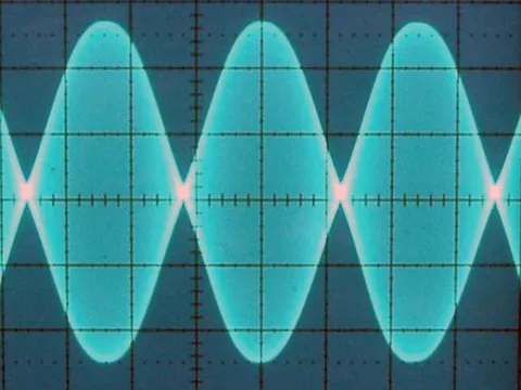
The two-tone test is the classic method: two tones (say 700 and 1900 Hz) are fed in simultaneously, and the envelope on the oscilloscope immediately shows whether the amplifier is linear. Flattened peaks mean flat-topping — the amplifier is in compression and the signal is getting wide.
Without a scope you can still get a long way with an SDR and some distance: a second receiver a few hundred metres away, a look at the waterfall, a comparison of signal width with and without the amplifier. If the signal gets noticeably wider with the amplifier in line, something is wrong — usually the drive level.
Harmonics are the other issue. An amplifier without an effective output filter produces the second harmonic of 14 MHz at 28 MHz and the third at 42 MHz — right in the range where § 17 AFV demands 60 dB of suppression. Commercial amateur amplifiers have band filters built in and switched along; in homebrew designs the low-pass filter is the last component to economise on. And if band switching is manual: transmitting on 20 m with the amplifier still set to 40 m is the most reliable way to destroy the filter and your reputation in one go.
Cooling and power supply
Heat. At 60 percent efficiency, 1000 watts of RF output comes with around 700 watts of waste heat — a small fan heater in the shack, noticeable in summer and guaranteed during a contest. Forced-air cooling is mandatory, the airflow must stay unobstructed (so not inside a closed rack without extraction), and the fan should keep running after transmit. On a tube amplifier that run-on is not a comfort feature: without cooling after shutdown the tube suffers.
Mains supply. 1000 W of RF at 60 percent efficiency means roughly 1.7 kW input, about 7.5 amps at 230 volts under continuous carrier. On paper that fits a 16 A circuit (3.68 kW), but:
- Dedicated circuit. Amplifier, PC, transceiver and the fridge on the same breaker is a bad idea.
- Inrush current. The toroidal transformer in a tube amplifier draws 60 to 100 A briefly at switch-on. A type-B breaker will trip; type C holds. Many units include a soft-start — if yours does not, retrofit one.
- Voltage sag. If the mains voltage visibly dips on transmit (lights flicker), the supply wiring is too thin. That costs output power and stresses the amplifier.
- Residual current device. Interference-suppression capacitors to PE produce leakage currents; several devices together can trip a 30 mA RCD. That is not a reason to bypass the RCD — it is a reason to spread the equipment over several circuits.
The same applies with knobs on for portable and emergency operation: a 500 W amplifier from batteries or an off-grid supply draws around 70 A at 13.8 V — size cable and fuses accordingly.
Safety: high voltage, RF and exposure
High voltage
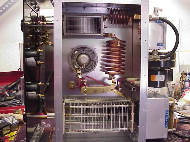
Lethal danger. Tube amplifiers run on 2000 to 4000 volts DC. The charge in the filter capacitors survives switch-off and unplugging — depending on the state of the bleeder resistors, for minutes. Reaching into the chassis without measuring first can kill you.
The rules are short and not negotiable:
- unplug, wait, measure — do not trust the bleeder resistor, it may be open
- discharge any residual voltage through a resistor on an insulated discharge stick, not by shorting it with a screwdriver
- never defeat the cabinet interlock, not even "just to measure"
- one hand in your pocket, never work alone on an open amplifier
- measure the plate voltage again after discharging, before reaching in
RF burns and RF in the shack
RF burns are treacherous because they go deep and barely hurt while they happen. Antennas, open feed lines and balun terminals do not get touched while transmitting. Full stop.
A related symptom is RF in the shack: tingling microphones, erratic keyboards, displays that reboot on transmit. That is not an amplifier fault but a common-mode problem that higher power merely makes visible. The cure: common-mode chokes on the feed line and control cables, and clean bonding — the common-mode indicator helps track it down.
RF exposure
Unlike Germany, where the BEMFV requires a documented site declaration above 10 W EIRP, the Austrian AFV has no dedicated RF exposure clause. That is not reassurance; it puts the responsibility entirely on the operator. The ICNIRP reference levels, which also underpin the German rules, serve as the yardstick. In practice, at kilowatt levels:
- Distance. In the far field, field strength falls linearly with distance — double the distance, half the field. A few extra metres between antenna and living space beat any amount of debate.
- No kilowatt balcony antenna. A loop or vertical within arm's reach is a compromise at 100 W and a problem at 1 kW — for your own family as much as for the neighbours.
- Consider all simultaneous transmissions together if several antennas are operated in parallel.
- Freely available calculators such as this RF exposure distance calculator give useful ballpark figures — the German limits are a sensible benchmark even without an Austrian obligation.
Grounding, bonding and lightning protection
The section that generates the most confusion — because three entirely different things share one word.
- Protective earth (PE). The green-and-yellow conductor from the wall socket. It ensures the breaker trips in a fault. It is never disconnected — not even with a "ground lift" adapter to cure a hum loop. Do that and you have built a lethal fault into your shack.
- Bonding. All equipment chassis — transceiver, amplifier, tuner, power supply — are tied to a common bus bar with short, wide conductors (copper strap, braid). What matters is not DC resistance but inductance: a two-metre length of thin wire is not a ground at 14 MHz, it is a choke.
- RF counterpoise. What some call an "RF ground" is, with unbalanced antennas, actually part of the antenna system. A ground rod does not replace radials.
- Lightning protection. A field of its own with its own standards (ÖVE/ÖNORM EN 62305). Key points: a single entry point for all cables into the building, surge arresters on a bonded bus bar at exactly that point, and physically disconnecting the coax during thunderstorms. Details in our article on station grounding and lightning protection, and for antenna supports in towers and masts.
For the amplifier specifically: it is the heaviest and best-grounded box in the shack, and therefore often the point where all currents meet. A clean star bonding scheme to a common bar — not daisy-chained device to device — saves a great deal of troubleshooting later.
Commissioning, step by step
- Connect a dummy load. Check its rating — many dummy loads take 1 kW for only a few seconds. § 14 AFV requires tuning without unnecessary radiation.
- Measure the PTT line. Open-circuit voltage at the amplifier's keying jack; above 12 V, connect only through a buffer.
- Amplifier on standby, transceiver at low power, check the antenna SWR without the amplifier — ideally measured beforehand with a NanoVNA.
- Set the band correctly — on both transceiver and amplifier. With automatic band switching, verify once that it actually follows.
- Tuning a tube amplifier: dip the plate current with TUNE, then bring up output with LOAD, then retouch TUNE. Short key-downs, do not sit in the dip for minutes.
- Raise the drive until rated output is reached — and stop there. Note the transceiver power setting per band.
- Switch to the antenna, check SWR, then go to full power.
- Set up digital modes separately: halve the power, watch the ALC indicator, reduce the audio level from the PC until no ALC action occurs.
Market overview 2026
HF, solid state (LDMOS)
- SPE Expert 1.3K-FA / 2K-FA — Italian, very widespread, built-in tuner and automatic band following; the 1.3K-FA is the reference in its class
- Elecraft KPA1500 — 1.5 kW with integrated ATU, excellent documentation, expensive in Europe
- Palstar LA-1K — 1 kW, robust, good value
- RF-KIT RF2K-S — German kit in the 2 kW class with a large, active user community; permitted as a kit under the RED exemption
- RM Italy BLA-350 Plus — 300 W, 1.8–30 MHz, compact and affordable; a good way to step from 100 to 300 W
- Juma PA1000 — Finnish, 1 kW, deliberately simple
HF, tube
- ACOM 1000 / 1010 / 1200S — Bulgarian, robust, widespread, good spares situation
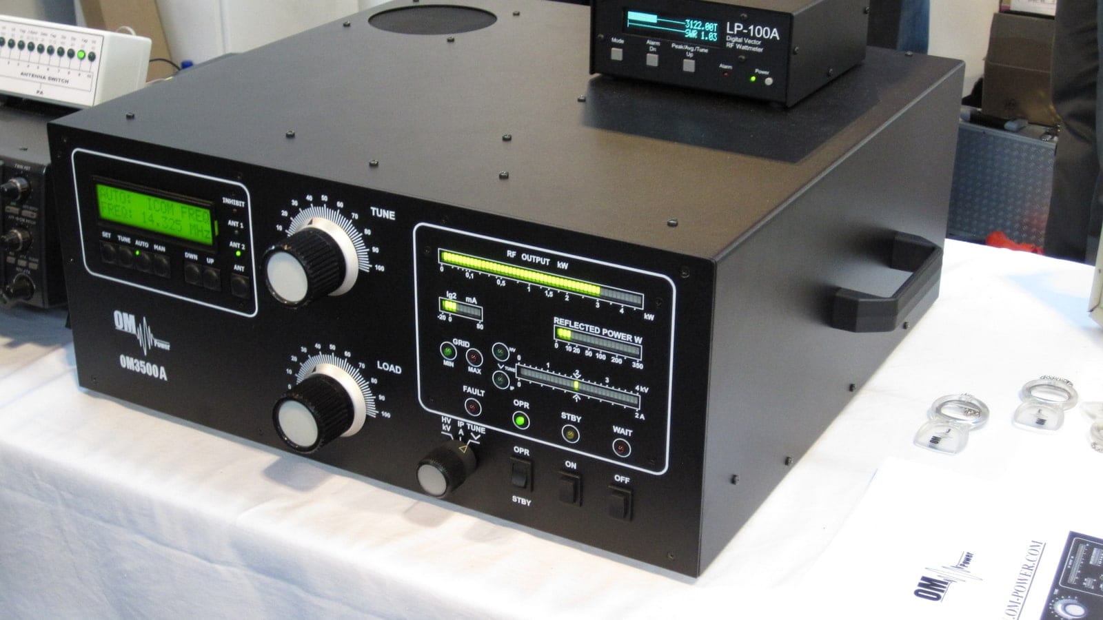
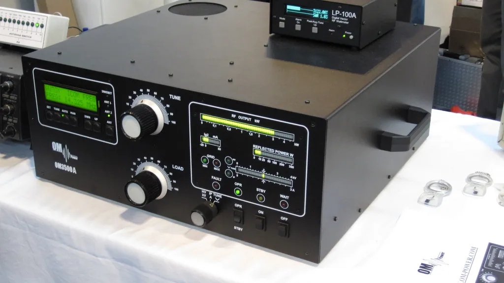
- OM Power OM2500 / OM3500A — Slovak, very solid, common in contest stations
- Ameritron AL-811H — 800 W, the affordable classic with four 811A triodes; simple, loud, repairable
VHF/UHF
- BEKO HLV series (HLV-350, HLV-1000, HLV-1100, HLV-2000) — German manufacture for 2 m, 70 cm and 23 cm with circulator protection; the 23 cm variant is of limited use in Austria because of the 10 W limit
- Mirage series — compact mobile and portable amplifiers in the 100 W class
Stay away from CB "burners". Amplifiers from the CB world — including the RM Italy KL series — are built for 27 MHz, have no band-selective filtering and produce harmonics and intermodulation far beyond what § 17 AFV allows. They are unsuitable for amateur service regardless of the wattage on the data sheet.
Used-buying checklist
- ask about tube hours and check idle current — a soft tube no longer makes rated output
- clarify tube availability before buying. For Russian types (GU-74B, GU-78B) that has been a serious question since 2022.
- check the relays by ear and by eye — contacts burnt by hot switching are the most common hidden damage
- check vacuum variable capacitors for loss of vacuum (arcing while tuning)
- fans and airflow — dust in the chimney is a slow death sentence for a tube amplifier
- switch through all band filters and measure on each band at low power into a dummy load
- for LDMOS: test the protection circuits — into a slightly mismatched load the unit must shut down, not burn out
- check power supply and transformer for hum, smell and corrosion; a failed HV transformer is often an economic write-off
The most common mistakes at a glance
- bought the amplifier before finishing the antenna
- connected the PTT line to a modern transceiver without a buffer
- used ALC as a power control instead of the transceiver's output setting
- ran FT8 at full power until the module gave up
- put the tuner between transceiver and amplifier instead of after it
- changed band on the transceiver but not on the amplifier
- disconnected protective earth to cure a hum
- 1 kW into a balcony antenna two metres from the children's room
- ran High Power without authorisation — the application is a formality, the lack of it is not
Sources and further reading
- Fernmeldebüro: information on applying "High Power" to radio amateurs — the authoritative statement on application and prerequisites
- Amateurfunkverordnung (AFV) in the RIS — §§ 13, 14 and 17 as currently in force
- BGBl. II No. 61/2023 — amendment to the Frequenznutzungsverordnung 2013
- ÖVSV band plan overview (PDF) — frequency allocations and power limits on one page
- W8JI: Relay Interface System for HF Amplifiers — relay timing, hot switching and keying lines in detail
- KK5DR: Tune-up Procedure for HF Amplifiers (PDF) — a proven tuning procedure for tube amplifiers
- RF exposure distance calculator — far-field assessment for amateur antennas (German)
Related articles on oeradio.at
- Station grounding and lightning protection
- EMC guide: finding and fixing interference
- Frequency utilisation ordinance: what has changed
- Which licence class is right for me?
- EME: moonbounce on 2 m and 70 cm
- SO2R: single operator two radio for contesters
- QRP: around the world with 5 watts — the counter-experiment to this article
73 – your oeradio.at editorial team
Image credits
- Title image: OM Power OM3500A — photo: Karl-Martin Skontorp, Wikimedia Commons, CC BY 2.0
- Collins 30L-1 — photo: RadiomanPA, Wikimedia Commons, CC BY-SA 3.0
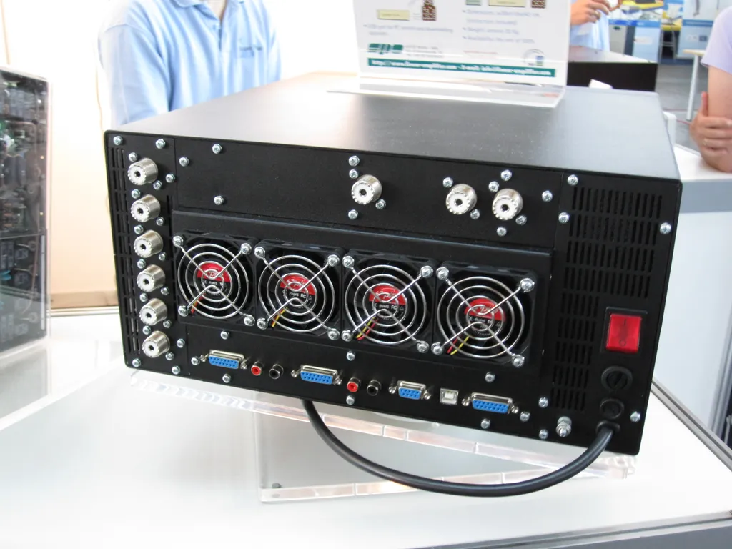
- SPE Expert 2K-FA, rear — photo: Karl-Martin Skontorp, Wikimedia Commons, CC BY 2.0
- Two-tone linearity test — photo: Cqdx, Wikimedia Commons, CC BY-SA 3.0
- 3CX1500A7 interior — photo: RSAG, Wikimedia Commons, CC BY-SA 3.0
Transparency Notice
This article was researched and written with the support of AI (Claude, Anthropic). The images come from Wikimedia Commons under free licences (credits above). The embedded videos are third-party content; the respective channels are responsible for them. Statements about the legal situation reflect the position as of August 2026 and do not constitute legal advice — the binding text is the current version of the FNV and AFV in the RIS. Corrections and additions are welcome at [email protected].