
Table of Contents
- What Is a Magnetic Loop?
- Advantages — Why the Magnetic Loop Is So Popular
- Disadvantages — The Other Side of the Coin
- Typical Dimensions by Band
- Key Components
- The Main Loop
- The Variable Capacitor
- The Coupling Loop
- The Tuning Mechanism
- Practical Building Tips
- Common Mistakes
- Commercial Magnetic Loops
- Performance Compared to Wire Antennas
- Best Practices for Balcony Operation
- Tips Specific to Austria
- Transparency Notice
If you live in a rented flat or apartment, you know the problem: a Yagi on the roof? Not a chance. A dipole in the garden? What garden? For many radio amateurs in urban areas, the dream of HF operation seems to die at the front door. But there is a solution that fits on any balcony — the Magnetic Loop Antenna.
What Is a Magnetic Loop?
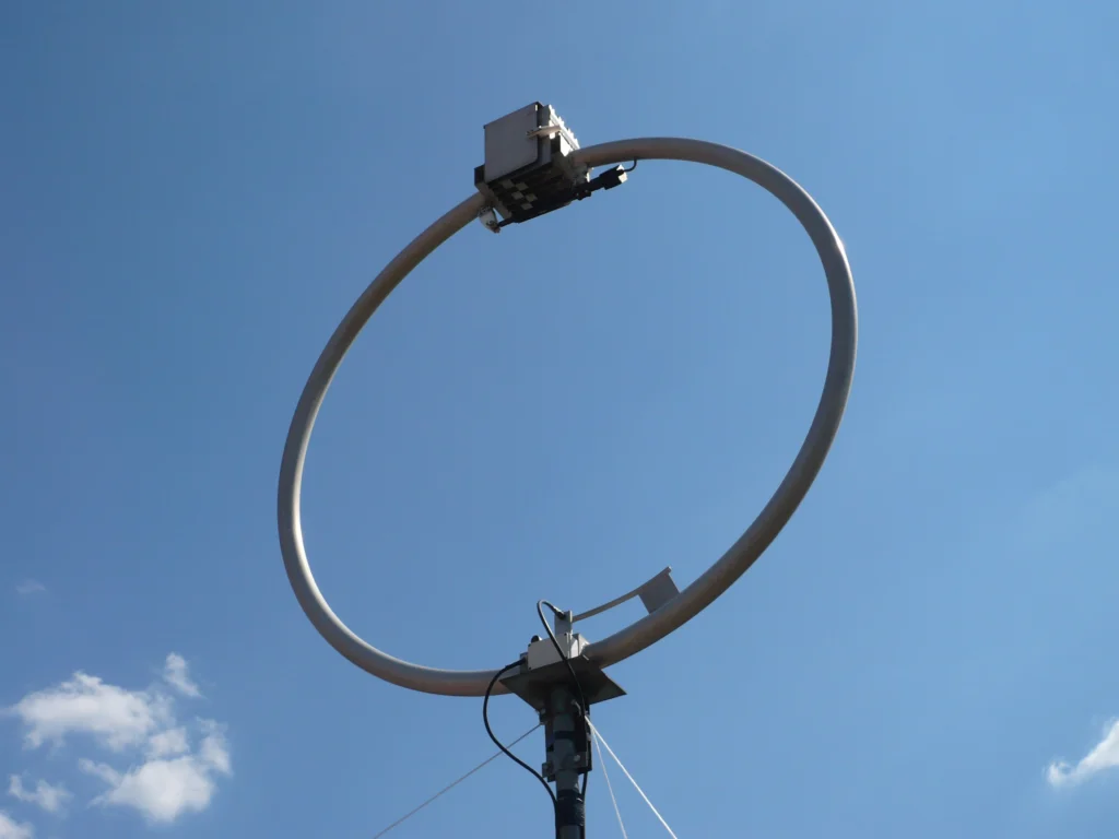
A Magnetic Loop — also called a Small Transmitting Loop (STL) — is essentially an LC resonant circuit that works as an antenna. The principle is beautifully simple: take a loop of copper or aluminium tubing and connect it to a variable capacitor. Together they form a resonant circuit that can be tuned to a specific frequency.
The main loop typically has a circumference of about one tenth to one fifth of the wavelength — far smaller than a dipole. Energy is coupled in via a smaller coupling loop (roughly one fifth of the main loop's diameter), which is connected directly to the coaxial cable. This coupling loop transforms the transceiver's 50-ohm impedance to the impedance of the main loop.
The special characteristic: a Magnetic Loop responds primarily to the magnetic component of the electromagnetic field — hence the name. This makes it relatively insensitive to electrical noise, which is omnipresent in residential areas.
Advantages — Why the Magnetic Loop Is So Popular
- Extremely compact: A loop for the 20-metre band has a diameter of just 0.7 to 1.7 metres. Usable on a balcony, in an attic, or even indoors.
- No radials needed: Unlike vertical antennas, the Magnetic Loop requires no ground system and no radials. Just set it up and tune it.
- Low noise pickup: Because it responds to the magnetic rather than the electric field, it picks up significantly less QRM. In an urban environment, this can mean 2-3 S-units less noise.
- Multi-band capable: By retuning the variable capacitor, a single loop can cover several bands — typically over a frequency range of 3:1 to 4:1.
- Stealth factor: A Magnetic Loop does not look like an antenna. Especially as a circle of copper tubing, it can be mounted inconspicuously on a balcony — no trouble with the landlord.
- No guying required: No mast, no ropes, no ground stakes. Set up, connect, operate.
Disadvantages — The Other Side of the Coin
The Magnetic Loop is not a miracle worker. There are limitations you should be aware of:
- Extremely narrow bandwidth: The 3 dB bandwidth on 40 m is only about 5 to 30 kHz. Switching from CW to SSB requires retuning. Even changing frequency within a mode often requires retuning.
- Constant retuning: Every frequency change requires readjustment. A motorised drive (stepper motor) is virtually essential for comfortable operation.
- High voltages at the capacitor: At 100 watts of transmit power, voltages of 5,000 to 10,000 volts appear at the variable capacitor. This demands a high-quality vacuum variable capacitor and absolute caution.
- Limited power handling: Most home-built loops handle 25 to 100 watts. QRO operation requires special components.
- Lower efficiency: Compared to a resonant dipole at optimal height, the Magnetic Loop has lower efficiency. On the lower bands (80 m, 160 m), losses can be substantial.
- RF safety: The high voltages and strong near-fields require a safety distance. Do not touch while transmitting!
Typical Dimensions by Band
The following gives guidance on loop diameter for each band:
- 80 m (3.5 MHz): 2.5 to 4.0 metres diameter. Quite large — better suited for a garden or attic.
- 40 m (7 MHz): 1.5 to 2.5 metres. Still workable on a large balcony, ideal for roof terraces.
- 20 m (14 MHz): 0.7 to 1.7 metres. The sweet spot — compact enough for almost any balcony, with good efficiency.
- 15 m / 10 m (21-28 MHz): 0.5 to 1.0 metres. Very compact, works excellently during good propagation.
Rule of thumb: the larger the loop relative to the wavelength, the higher the efficiency. For the 20-metre band, a diameter of about one metre is a good compromise between size and performance.
Key Components
The Main Loop
The heart of the antenna is the conductor loop. Copper tubing with a diameter of 15 to 22 mm is ideal — the thicker the better, because a larger conductor cross-section means lower ohmic losses and thus higher efficiency. Copper has lower resistance than aluminium and is therefore the first choice. In hardware stores, you will find 15 mm and 22 mm copper tubing sold by the metre in the plumbing section — typically around 8 to 15 EUR per metre.
The Variable Capacitor
This is where things get critical: the capacitor must withstand the high RF voltages. For serious loops at 50 watts and above, a vacuum variable capacitor is essential. On eBay, at hamfests, or through amateur radio flea markets, you can find Russian vacuum variable capacitors (e.g. type KP1-4) for 30 to 80 EUR. For QRP operation (under 10 watts), a butterfly capacitor or a high-quality air-spaced variable capacitor may suffice.
The Coupling Loop
The coupling loop typically has a diameter of about one fifth of the main loop. It is made from coaxial cable or thinner copper tubing and positioned opposite the capacitor. Correct sizing of the coupling loop is critical for good impedance matching — a NanoVNA (see our article on that topic) is enormously helpful here.
The Tuning Mechanism
Because of the narrow bandwidth, a stepper motor for remote tuning is almost indispensable. Stepper motors with Arduino control and remote operation are available as kits from about 20 EUR. This lets you tune the capacitor comfortably from your shack without going out to the balcony every time.
Practical Building Tips
- Maximise conductor diameter: 22 mm copper tubing instead of 15 mm gives noticeably better efficiency. The difference can be 1 to 2 dB — and that is perceptible.
- Minimise joints: Every solder joint, every mechanical connection is a source of loss. Ideally the loop consists of a single piece of bent tubing.
- Use silver solder: If soldering is necessary, use silver solder rather than standard soft solder. The lower resistance makes a difference at RF.
- Use an antenna analyser: A NanoVNA is worth its weight in gold when building a Magnetic Loop. Resonant frequency, impedance, and SWR can be observed in real time.
- Weatherproofing: Copper oxidises over time (verdigris). A clear lacquer or UV-resistant coating protects the surface. Cover the capacitor and electrical connections with a weatherproof enclosure.
- Prefer a round shape: A circular loop has the best efficiency, followed by octagonal and square shapes. Bending copper tubing works best with a pipe bender or the sand-fill method.
Common Mistakes
- Conductor too thin: Using wire instead of tubing dramatically lowers efficiency. Minimum 8 mm diameter, 15 mm or more is better.
- Poor capacitor connections: The junction between tubing and capacitor is the most critical point. Loose screw connections or oxidised contacts ruin performance.
- Wrong capacitor type: Simple air-spaced variable capacitors arc over at higher power. You need a type that provides the necessary voltage rating.
- Coupling loop wrongly sized: Too large or too small results in poor matching. Rule of thumb: one fifth of the main loop diameter as a starting point, then optimise with a NanoVNA.
- Mounting on metal: Metal railings, sheet-metal facades, or metal frames in close proximity detune the loop and significantly reduce efficiency. Maintain at least 50 cm clearance.
- Capacitor at the bottom: The capacitor belongs at the top of the loop, opposite the coupling loop. This way, the highest voltages are as far as possible from people and conducting surfaces.
Commercial Magnetic Loops
If you prefer not to build your own, ready-made solutions are available:
- MFJ-1786 (Super Hi-Q Loop): 36-inch loop for 10 to 30 MHz, motorised tuning, up to 150 watts. Around 500 to 600 EUR. Well proven and widely used.
- Chameleon CHA F-LOOP 2.0: Portable loop for 6.9 to 29.7 MHz, up to 25 watts. About 350 to 400 EUR. Excellent for portable operation and POTA/SOTA.
- AlexLoop Walkham: Ultra-lightweight portable loop (600 g) for 7 to 29 MHz, up to 20 watts. Approximately 250 to 300 EUR. The classic for travel and hiking.
- Ciro Mazzoni Baby Loop: High-quality Italian craftsmanship, models from 3.5 to 30 MHz, up to 100 watts. From about 400 EUR. Superb build quality — Made in Italy has its price, but also its quality.
All prices mentioned are approximate and may vary depending on retailer and availability.
Performance Compared to Wire Antennas
Let us be honest: a Magnetic Loop is not a performance-equivalent alternative to a resonant dipole at 10 metres height. Depending on band and loop size, the loss is 6 to 15 dB compared to an optimally mounted dipole. That sounds like a lot — and on paper, it is.
In practice, however, the calculation often looks different: in an urban environment, the Magnetic Loop has a significant noise advantage. While a dipole at 5 metres height over a residential area picks up S7 to S9 noise, the loop often shows only S3 to S5. This noise advantage of 2 to 4 S-units compensates for part of the signal loss. The signal-to-noise ratio — and that is ultimately what matters — can be quite comparable.
Digital modes like FT8 and CW are where the Magnetic Loop truly shines. FT8 decodes signals down to -24 dB below the noise floor — absolute signal level becomes secondary. Many balcony operators regularly work DX on 20 m and 17 m using a Magnetic Loop and FT8.
Best Practices for Balcony Operation
- Distance from the wall: At least 50 cm, preferably more. Concrete walls with reinforcing steel absorb RF energy and detune the antenna.
- Distance from metal railings: Metal balcony railings and parapets can detune the loop and drastically reduce efficiency. If possible, let the loop extend beyond the railing.
- Limit power: On a balcony, 25 to 50 watts is a sensible upper limit. More power creates stronger near-fields — consider EMF safety and your neighbours.
- Capacitor on top: The highest voltages occur at the capacitor. It belongs at the top of the loop, as far away from people as possible.
- Observe RF safety distances: At 50 watts, the distance to a person's head should be at least 1.5 to 2 metres. Follow your national amateur radio association's EMF guidelines.
- Vertical vs. horizontal polarisation: Mounted vertically, the loop radiates with horizontal polarisation (and vice versa). For HF DX, horizontal polarisation is standard — so mount the loop vertically.
Tips Specific to Austria
Good news for Austrian radio amateurs: a small Magnetic Loop on a balcony generally requires no building permit. Since it does not constitute a permanent structural change and is visually unobtrusive, it normally does not fall under the building regulations of the federal states. Of course, in rented accommodation you should inform the landlord — but most have no issue with an inconspicuous copper ring on the balcony.
Sourcing materials: Copper tubing (15 mm and 22 mm) is available at any Bauhaus, OBI, or Hornbach hardware store. For a loop of 1 metre diameter, you need about 3.15 metres of tubing — costing roughly 25 to 45 EUR depending on diameter. Vacuum variable capacitors can be found on eBay, at hamfests, or through OE amateur radio forums.
The EMF self-declaration has become relevant for radio amateurs since the implementation of the EU directive. With a Magnetic Loop at moderate power (under 50 watts), the limits are generally not an issue, but you should still prepare the documentation.
For apartment-dwelling operators in Vienna, Graz, Linz, Salzburg, and Innsbruck in particular, the Magnetic Loop is often the only realistic way to get on HF. Combined with FT8 or CW and 25 to 50 watts, surprisingly good results can be achieved. Many OE stations regularly work DX with this setup combination.
The Magnetic Loop is not a compromise antenna — it is an enabling antenna. It makes HF operation possible where nothing else would work. Keep your expectations realistic, respect the physics, build carefully, and you will have a great deal of enjoyment with a loop. And who knows — perhaps we will hear you on 20 metres from your balcony soon.
73 – your oeradio.at editorial team
Transparency Notice
This article was researched and written with the assistance of AI (Claude, Anthropic). Any illustrations used were generated with AI (ChatGPT/DALL·E, OpenAI) unless otherwise noted. The editorial team has reviewed and edited all content. Despite careful review, occasional inaccuracies may occur — we welcome corrections via email to [email protected].