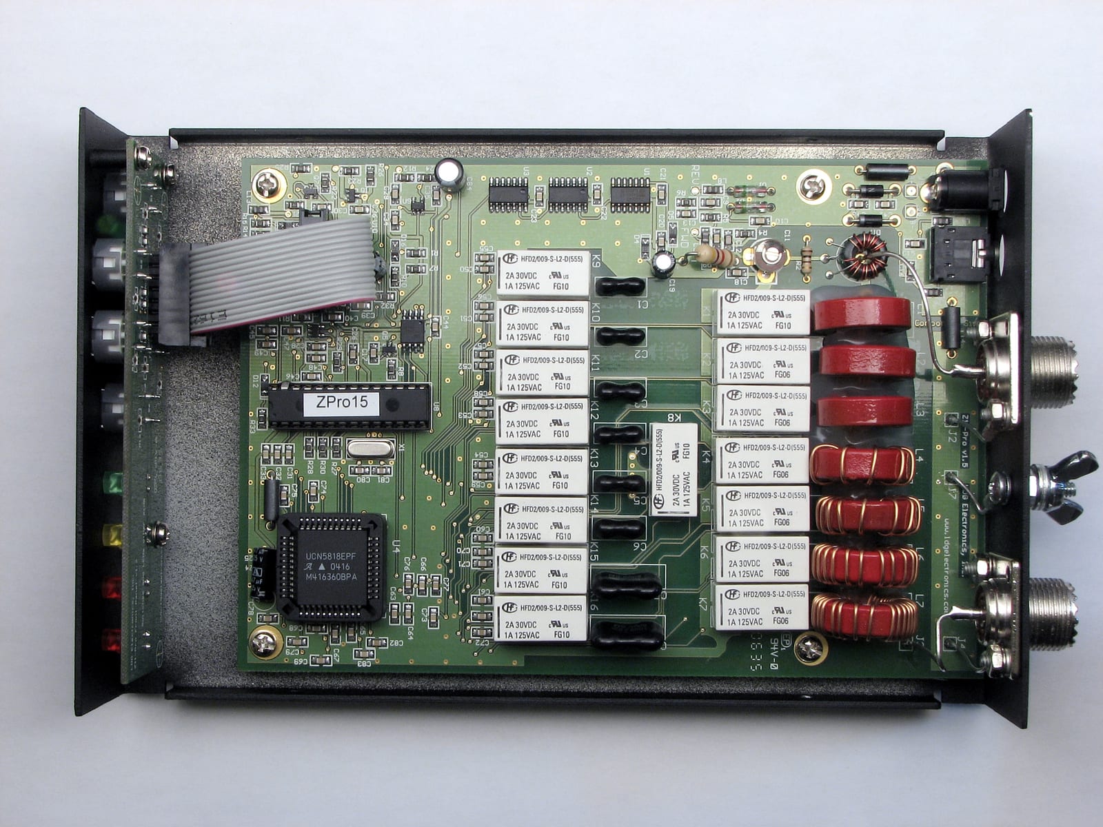
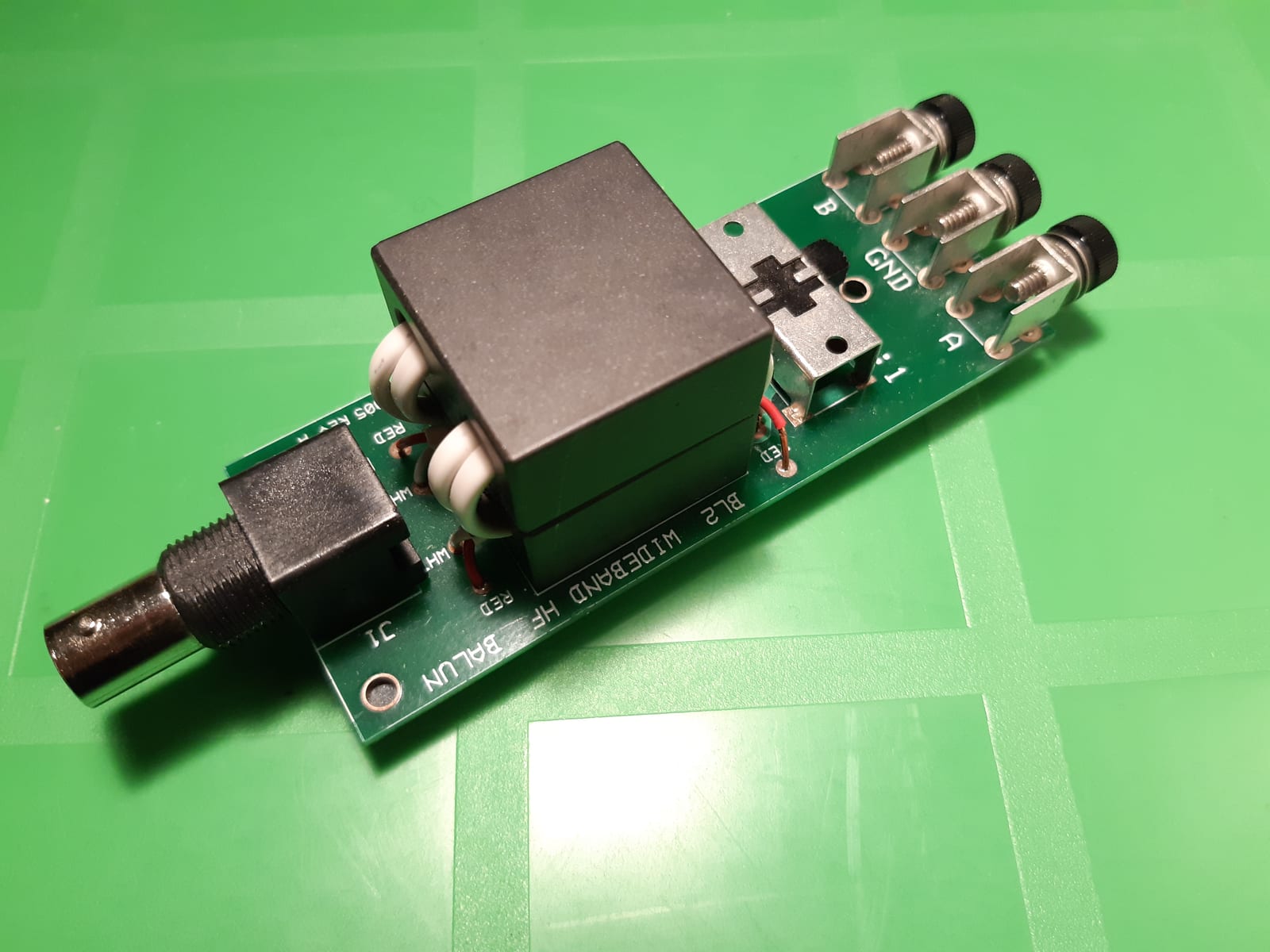
Few components in a shack are bought as often and understood as rarely as the balun. It is treated as a cure for poor SWR, for interference on the neighbour's television and for RF on the microphone. In truth it can fix only one of those three, and it does that one very well.
This article sorts the subject out: what a balun does and what an unun does, why the difference between current and voltage types decides between success and frustration, which ferrite mix suits which job, what the popular 49:1 on an EFHW really costs you, and how to measure all of it with a NanoVNA instead of taking it on faith.
The real problem: the third conductor
Electrically, coax has three conductors, not two. The centre conductor and the inside of the shield carry the wanted current. The outside of the shield is a conductor in its own right, and that is where the trouble starts. Feed something balanced like a dipole with it and part of the current returns along the outside of the cable towards the shack.
This common mode current is behind most of the complaints blamed on baluns: the feedline radiates, the pattern distorts, the SWR changes when you move the cable, the tuner suddenly finds different settings, RF appears on the microphone, the neighbour hears you in the speakers. Anyone hunting interference is chasing exactly this nine times out of ten.
Balun and unun, kept apart
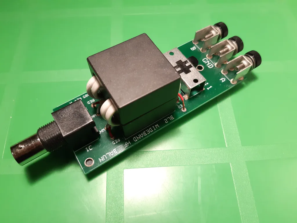
Balun stands for balanced to unbalanced. It sits between something balanced, a dipole for instance, and an unbalanced feedline. A balun may also transform impedance, but it does not have to: the common 1:1 balun transforms nothing, it only provides a clean transition.
Unun stands for unbalanced to unbalanced. It joins two unbalanced systems and transforms impedance only. The typical case is the 9:1 for a random length wire, which is no fun at all without a proper counterpoise.
Current balun or voltage balun
This is the distinction everything hinges on in practice, and it is printed on almost no packaging.
The voltage balun after Ruthroff forces equal and opposite voltages at its two outputs. That sounds sensible, but it only helps as long as the load really is balanced. As soon as one dipole leg runs closer to the roof than the other, as soon as the antenna turns reactive or is used off resonance, the currents divide unevenly and the remainder flows back along the outside of the cable. A voltage balun barely suppresses common mode current at all.
The current balun after Guanella forces equal and opposite currents instead. It lets the output voltages float and presents a high impedance to common mode current. That keeps it honest even when the antenna hangs asymmetrically, which in real gardens is the normal case.
Hence the rule of thumb worth remembering: when in doubt, current balun. If you need both impedance transformation and choking, put a 4:1 voltage balun and a separate 1:1 choke in series, or use a 4:1 built the Guanella way in the first place.
The ratios
What is quoted is always the impedance ratio, and that is the square of the turns ratio. A transformer with two turns against fourteen has a turns ratio of 1:7 and therefore an impedance ratio of 1:49.
- 1:1 for the dipole and anywhere the transition simply needs to be clean.
- 4:1 for loads around 200 ohms, such as folded dipoles and some delta loops.
- 9:1 for long wires and random wires in the few hundred ohm range, always with a decent counterpoise.
- 49:1 for the end fed half wave, which sits at roughly 2,400 to 3,000 ohms at the feedpoint.
- 64:1 as a variant of the same design when the measured feedpoint impedance comes out higher.
The common mode choke
A common mode choke is electrically a 1:1 current balun that does nothing except present a high impedance to common mode current. The wanted signal inside the cable does not see it, because its fields cancel inside the coax. Only the current on the outside meets the ferrite.
The decisive question is how much choking impedance is needed. Below 1,000 ohms not much useful happens. Several kilohms across the bands you actually use is a workable target. In practice that means eight to twelve turns of RG-58, RG-8X or RG-213 on an FT240 sized core, depending on mix and band.
Placement matters just as much. One choke belongs at the feedpoint. A second one at the shack entry is often the more effective of the two, because it stops the RF where it couples into equipment and mains wiring. To find out whether there is common mode current at all, measure it with a common mode indicator before buying ferrite.
Which ferrite
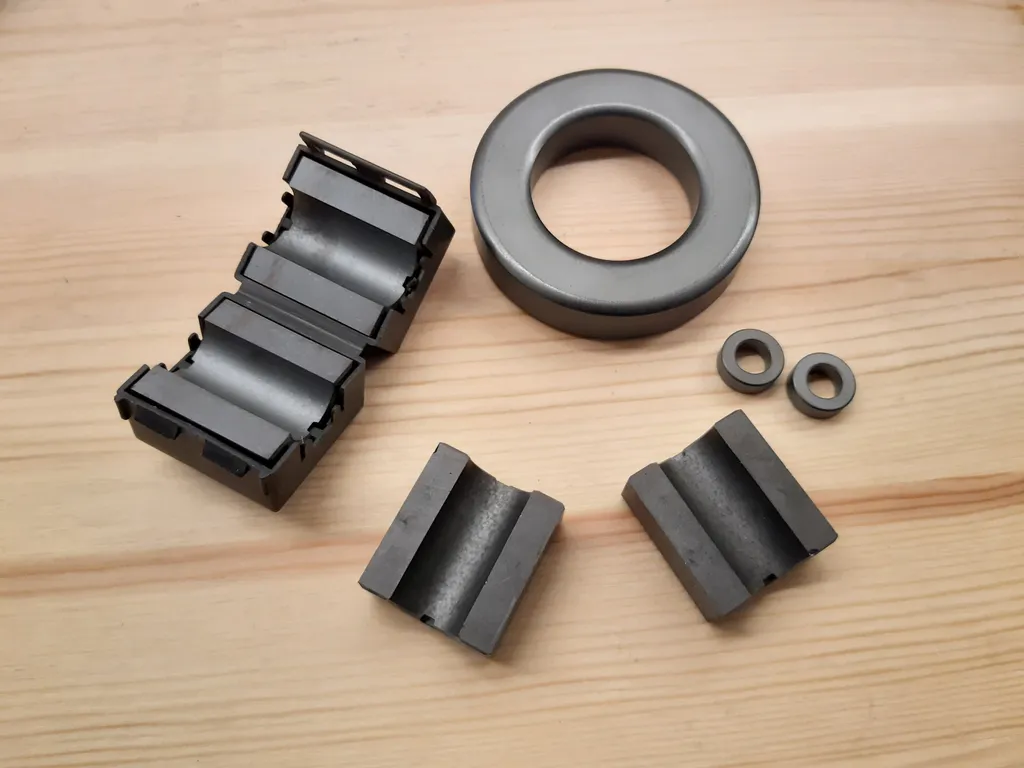
- Mix 31: first choice for common mode chokes from 160 through 10 metres, usefully effective across the whole range.
- Mix 43: the decades-old classic, permeability around 800, choking impedance peaking roughly between 8 and 15 MHz. As common in transformers as in chokes.
- Mix 52 and 61: sensible from about 10 MHz upwards and for builds aimed at the higher bands.
- Powdered iron such as mix 2: low loss and suitable for high power transformers, but useless as a common mode choke because the permeability is far too low.
A widespread misconception is that more cores are always better. Two stacked cores double the impedance but also push the self resonance of the winding downwards. On 10 metres a choke with too many turns can perform worse than one with fewer.
Winding
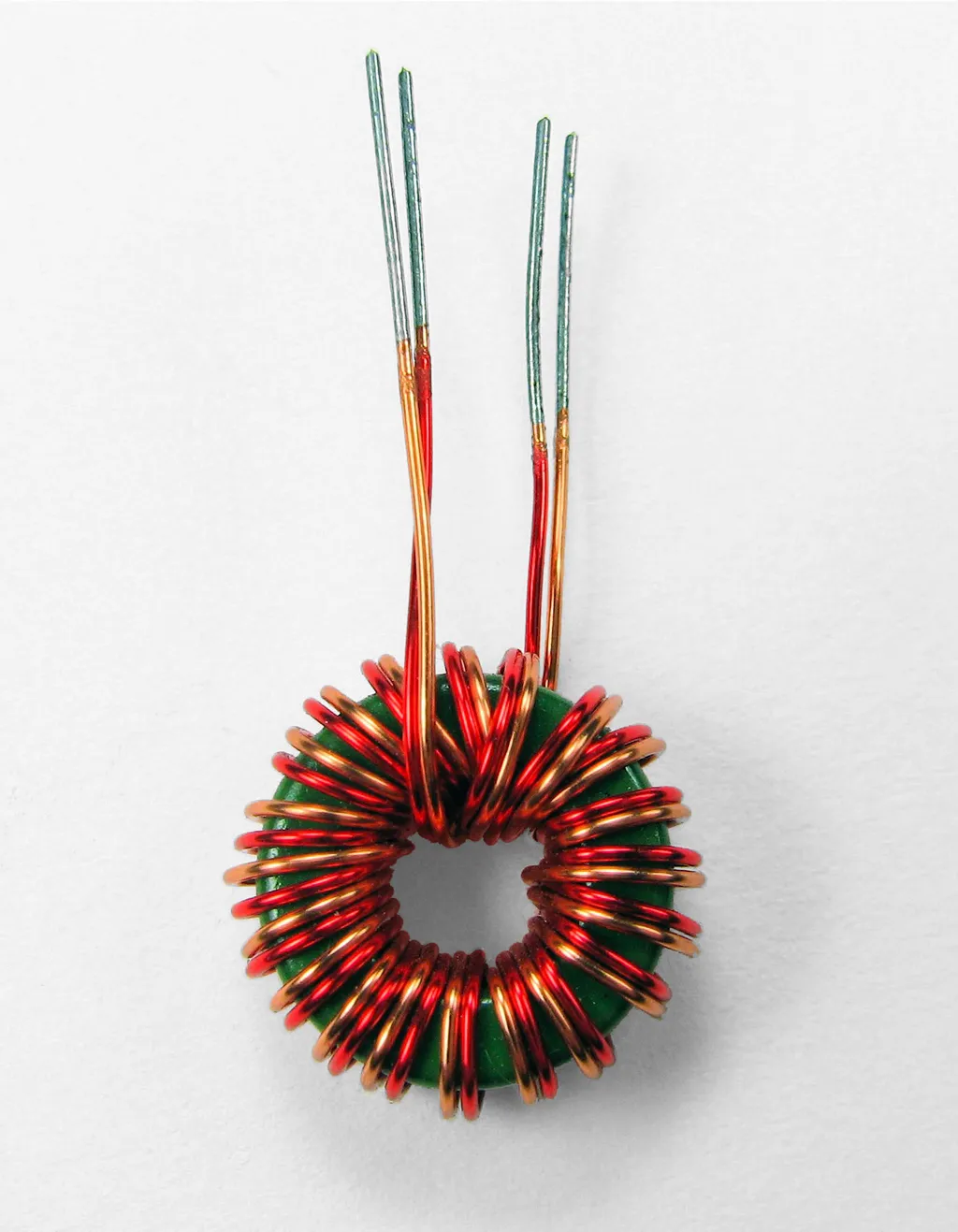
Transformers are wound bifilar, two wires in parallel, so the coupling stays as tight as possible. For the classic W1JR choke you pass the coax itself through the core instead, commonly two times five and a half turns of RG-58 on an FT140-43.
It also works without a core: the so-called ugly balun is a few turns of coax on a piece of pipe. It costs nothing but only works narrowband around the self resonance of the coil, and it is clearly inferior to a ferrite core. Fine as a field expedient, not as a permanent installation.
The 49:1 on an EFHW, honestly
No component has conquered as many shacks in recent years as the 49:1 transformer for the end fed half wave. It works, but it is not a magic trick, and the numbers are uncomfortably honest.
On 20 metres a monoband EFHW with a 49:1 on mix 43 runs with very low losses. On the higher bands from 17 through 10 metres, however, losses around 30 percent, roughly 1.5 dB, are well documented. The reason lies in the material itself, whose loss component rises noticeably above 10 MHz.
Two things help. Below 10 MHz a two-turn primary produces only about half the loss of a single-turn primary, which means considerably less heat at the same power. And duty cycle matters more than peak power: a small core forgives 100 watts of SSB, but not 100 watts of FT8 for hours.
Be careful with measurements. Many videos compare two transformers back to back or confuse average with peak power. It only becomes meaningful with a real load, with forward and reflected measurement, and with an eye on whether the core is warming up.
Video tip: typical mistakes with chokes, ununs and baluns in data mode operation, which is exactly where duty cycle turns into a problem.
Measure it, do not believe it
The performance of a common mode choke shows up clearly on a NanoVNA. You measure the impedance between the two shield ends, which is precisely the path common mode current would take. The result is often sobering: plenty of commercial chokes fall well short of their datasheet on individual bands.
Video tip (German): the measurement setup and how to read the result for a common mode choke on the NanoVNA, step by step.
Three stubborn myths
- A balun improves SWR. No. A 1:1 balun transforms nothing. If the reading changes after fitting one, that is because the feedline was radiating before and corrupting the measurement. The antenna is not better matched afterwards, it is merely measured honestly.
- A balun replaces the tuner. No. A transformer shifts impedance by a fixed ratio. Whatever is still off after that remains the tuner's job.
- Ferrite always helps. No. The wrong mix in the wrong place does little except get warm. And heat in the core is power that never reaches the antenna.
Video tip: the question it all comes down to, namely whether your particular antenna needs a balun at all.
What goes where
- Dipole, inverted V, doublet fed with coax: 1:1 current balun at the feedpoint.
- EFHW: 49:1 transformer plus a separate common mode choke about a tenth of a wavelength away, and a short counterpoise.
- Random wire: 9:1 unun, counterpoise not optional, choke behind it.
- Ladder line: a genuinely balanced tuner or a 4:1 current balun at the tuner output, never a voltage balun into the unknown.
- Vertical with radials: needs no balancing, but almost always a choke, otherwise the cable becomes part of the counterpoise.
- Magnetic loop: see the separate article, where the coupling loop does the matching.
Buy or build
Building your own is worth it because material and effort are modest: a core, some wire or coax, a weatherproof box. The real gain is knowing what is inside instead of trusting a label.
Commercial units make sense for high power or when the enclosure has to survive outdoors for years. Then two specifications are worth looking for, and both are often missing: the topology, current or voltage, and a power rating broken down by mode. A single number without a duty cycle says very little.
If you are planning the feedline as well, the cable types are covered in choosing coaxial cable and the matching losses in the attenuation calculator. What all of it does to the pattern can be explored in Antenna View.
Sources
- Guanella and Ruthroff topologies and their behaviour under unbalanced loads, as covered in the literature on broadband transformers
- Efficiency measurements of 49:1 and 64:1 transformers on mix 43, among others from the EFHW community
- Ferrite manufacturer datasheets for mixes 31, 43, 52 and 61
- hamwaves.com: Common Mode Chokes, a detailed treatment of choking impedance and construction
- N1FD: Power Losses and Dissipation in Various Ferrite Devices, losses and heating in practice
73 – your oeradio.at editorial team
Transparency Notice
This article was researched and written with the support of AI (Claude, Anthropic) based on publicly available sources, and the content has been editorially reviewed. It was substantially expanded in September 2026, in particular with the distinction between current and voltage baluns, the choice of ferrite mix, the question of how much choking impedance is needed and the loss analysis of the 49:1 transformer. The previous AI-generated lead image was replaced by a real photograph. All images come from Wikimedia Commons under free licences, with photographer and licence given in each caption. The embedded videos come from external YouTube channels and reflect their views. Figures for losses and choking impedance are orders of magnitude from published measurements and do not replace measuring your own build. Corrections welcome at [email protected].