Table of Contents
- The building blocks and what they cost
- The question to settle first: where does the filter go?
- Hands-on: band switching without manual work
- The signal at the DB1 connector
- The sketch
- The low-pass: turning PWM into DC voltage
- Careful with the pinouts
- What the alternatives are
- Drive: less is more
- From desk station to remote station
- Safety is the main point, not a footnote
- Legal situation in Austria
- Costs compared with the expensive solutions
- Conclusion
- Image credits and transparency notice
Guest article by Sergio, OE8CXC, with background research by the editorial team. The setup and the circuit are Sergio's; prices, sources, legal matters and safety were researched and marked as such by the editorial team.
The Hermes Lite 2 (HL2) is an open HF SDR for around 270 US dollars that can transmit on its own, but only with about 5 watts. If you want more, you need a power amplifier. The Xiegu XPA125B is an obvious choice: 100 watts, built-in tuner, compact case. Plugging it all together is quick, and then the real topic of this article begins: how does the amplifier find out which band the HL2 is currently transmitting on?
The building blocks and what they cost
The HL2 is a direct-sampling SDR with an AD9866 converter (12 bit, 80 MHz), an FPGA, Ethernet and a 5-watt power amplifier, developed in the Hermes-Lite project by Steve Haynal, KF7O (rtl-sdr.com). It speaks the openHPSDR protocol 1 and therefore runs with software such as Quisk, SparkSDR, Thetis or SDR Console. It is powered with 11 to 16 volts and at least 2 amperes (HL2 wiki).
New units are practically only available from Makerfabs. On 6 November 2026 the vendor's page listed 269 US dollars for the HL2, 52.80 US dollars for the N2ADR filter board and 16.90 US dollars for the enclosure, each without shipping and import VAT, and without saying whether the HL2 is assembled or a kit (Makerfabs). We did not find a vendor in the EU.
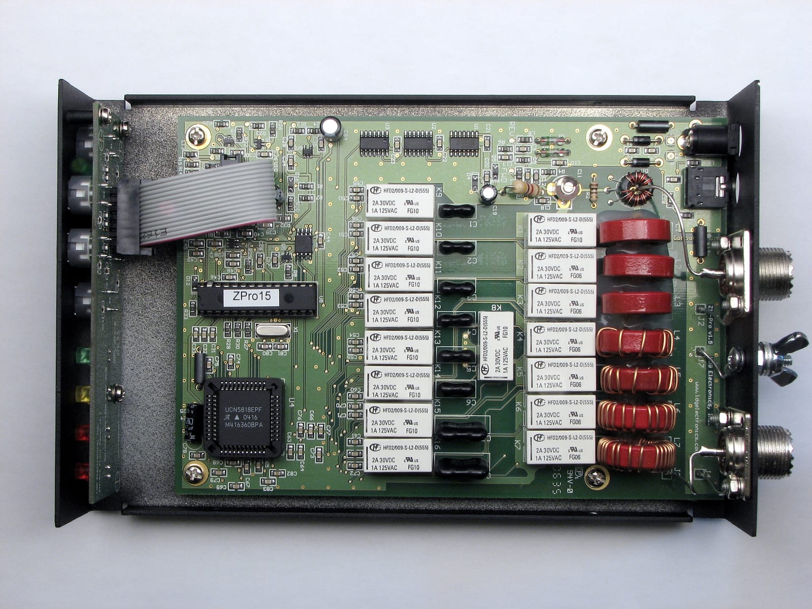
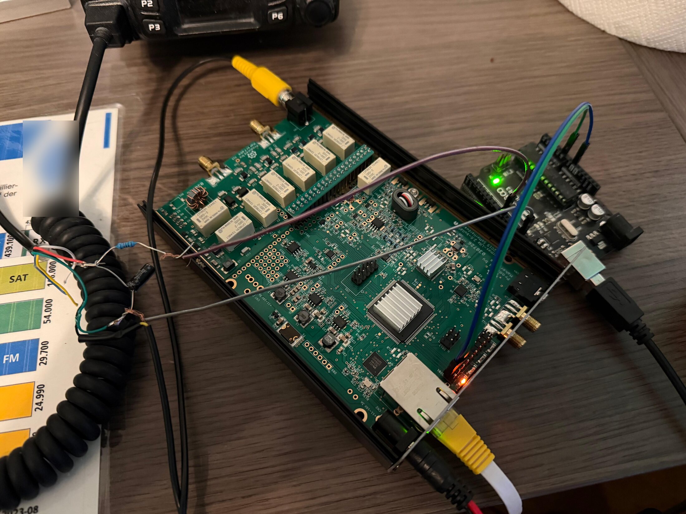
The N2ADR filter board by James Ahlstrom plugs onto the HL2. It adds switchable transmit low-pass filters for 160 to 10 meters, a high-pass filter for receive and a power measurement; control runs over the I2C bus (Ahlstrom). The relays of the board are easy to see in the photo below. The HL2 wiki recommends an aluminium profile as enclosure, which also cools the HL2's power amplifier (Enclosure and PA Heatsink). You should not transmit at onboard temperatures of 60 degrees or more.
According to its manual, the Xiegu XPA125B delivers at least 100 watts on 1.8 to 30 MHz and 80 watts on 6 meters, has 13 dB of gain, a built-in tuner (14 to 500 ohms) and no fan (manual). On 6 November, European dealers asked around 650 to 700 euros (hamradioshop.it, Passion-Radio, Pileupdx), a seller from China on eBay about 510 to 535 euros plus shipping and import charges, used from about 450 euros. The prices come from search results and dealer pages and may change.
Total cost. HL2, N2ADR board and enclosure together cost about 339 dollars, so roughly 300 euros (exchange rate assumed), plus shipping and 20 percent import VAT (our assumption, 70 to 110 euros). With an XPA125B (approx. 650 euros), a 13.8-volt power supply of about 25 amperes (approx. 50 euros) and a Pi or mini PC (approx. 60 to 80 euros, or a computer you already have) you end up at about 1,100 to 1,250 euros, or around 950 euros with a used amplifier. That is our rough calculation from the individual items; the power supply and Pi are estimated.
The question to settle first: where does the filter go?
The N2ADR board is built for the 5 watts of the HL2. Ahlstrom describes it as a filter that lets the HL2's 5-watt amplifier work as a complete QRP rig; the capacitors are rated for 5 watts into 50 ohms (Ahlstrom). The page says nothing about 100 watts through the board, and we found no measurement on this.
From this follows, and this is our conclusion, not a quotation: the filter board belongs in the 5-watt path between the HL2 and the amplifier and cleans up the drive signal. The 100 watts of the XPA125B must not run through the board. The harmonics the amplifier generates itself arise after this filter. For that, the XPA125B brings its own low-pass filters.
How good those are was measured by the ARRL test in QST 02/2023 (with a KX3 as driver, not with the HL2): on HF the harmonics were more than 61 dB below the carrier, on 6 meters they did not stay within the FCC limit. The two-tone test on 20 meters gave an IMD3 of only about -20 dB at 100 watts and about -28 dB at 80 watts. The lab therefore recommends backing off to about 80 percent. With 5 watts of drive, only 79 watts came out on 10 meters (ARRL test). According to our research, there is no measurement of the whole chain of HL2, N2ADR and XPA125B anywhere. Anyone with a spectrum analyzer can close a real gap here.
Hands-on: band switching without manual work
The XPA125B selects its filters and its tuner according to the band. With a Xiegu transceiver this happens automatically; with any other rig you have to change the band on the amplifier by hand with a button. For a setup that is later meant to run remotely, that is not a solution.
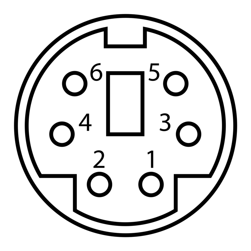
The amplifier expects the band information as a control voltage on its ACC socket, a six-pin mini-DIN socket. According to the ARRL test, PTT is on pin 2 (switched to ground), the band voltage on pin 3, the ALC signal on pin 4 and ground on pin 6. Anyone who applies 3.2 volts or more to the PTT line destroys the amplifier's processor, according to the ARRL. The HL2 does not output the band information as a voltage but as a PWM signal, a square wave whose pulse width depends on the band (this is how the HL2 community describes it, see kp4rx/hl2-xpa125b).
The signal at the DB1 connector
Sergio tapped the signal on the HL2 at the DB1 connectors. Here:
- Pin 2 = GND (ground)
- Pin 4 = the square-wave signal whose pulse width determines the band
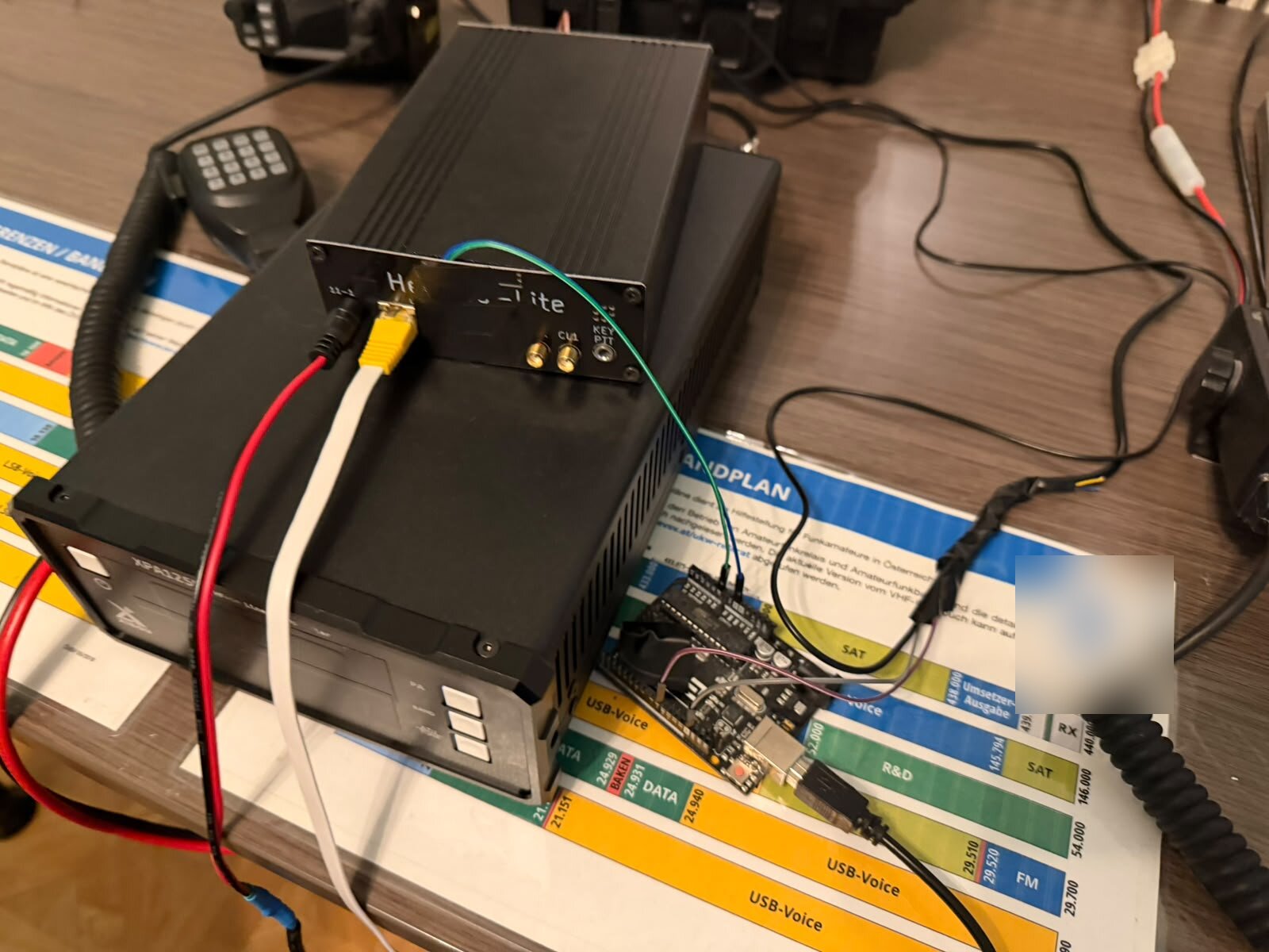
A processor evaluates the pulse width and assigns a band to it. In the photo below this is an Arduino-compatible board next to the HL2. Two wires (blue and green) lead to the DB1 pin header on the HL2 board, the other wires go to the cable towards the amplifier. The program for it is Sergio's own work.
The sketch
Here is Sergio's Arduino sketch in the original, including his comments. We did not build and test it ourselves. But it shows well how the principle works:
- Input
A0reads the square-wave signal from DB1 pin 4. The threshold is an analog value of 150 (out of a maximum of 1023). - The sketch uses
micros()to measure the time the signal is high and the period, and calculates the duty cycle from them. - The duty cycle is assigned to the nearest of ten bands (160 m to 10 m, from 6.7 to 70 percent). Sergio's table assigns each band its own PWM value, which according to his comment he measured.
- Only when the same band has been detected five times in a row does the sketch switch. This prevents flutter caused by measurement errors.
- The output runs via pin 9 with about 31 kHz PWM (timer 1 without prescaler). The smoothing to a DC voltage is done by the RC network behind pin 9. Without a detected signal the output goes to 0 V.
const int analogPin = A0;
const int xieguBandPin = 9;    // Pin 9 (31kHz)
const int threshold = 150;

struct Band {
  float duty;
  const char* name;
  int pwmValue;        // Deine ausgemessene, bombensichere Mitte
};

// Die perfekten Duty-Cycles kombiniert mit der sicheren PWM-Mitte
Band bands[] = {
  {6.7,  "160m", 9},   // Bereich: 0 - 18
  {13.3, "80m",  25},  // Bereich: 19 - 31
  {20.0, "60m",  37},  // Bereich: 32 - 43
  {27.0, "40m",  49},  // Bereich: 44 - 55
  {34.0, "30m",  62},  // Bereich: 56 - 68
  {43.0, "20m",  74},  // Bereich: 69 - 80
  {48.0, "17m",  87},  // Bereich: 81 - 93
  {57.0, "15m",  99},  // Bereich: 94 - 104
  {62.0, "12m",  111}, // Bereich: 105 - 117
  {70.0, "10m",  123}  // Bereich: 118 - 129
};
const int numBands = 10;

int lastConfirmedBand = -2;
int currentCandidate = -2;
int candidateCount = 0;
const int REQUIRED_MATCHES = 5;

void setup() {
  Serial.begin(115200);

  pinMode(LED_BUILTIN, OUTPUT);
  digitalWrite(LED_BUILTIN, LOW);

  pinMode(xieguBandPin, OUTPUT);

  // 31 kHz PWM auf Pin 9 (glättet das Signal mit deinem 104-Kondensator perfekt)
  TCCR1B = (TCCR1B & 0b11111000) | 0x01;
  analogWrite(xieguBandPin, 0);

  Serial.println("System bereit. Warte auf Signal...");
}

void loop() {
  unsigned long timeout = 20000;
  unsigned long waitStart;
  bool signalErkannt = true;

  // DEINE FUNKTIONIERENDE EINLESE-LOGIK (Unangetastet!)
  waitStart = micros();
  while(analogRead(analogPin) > threshold) {
    if(micros() - waitStart > timeout) { signalErkannt = false; break; }
  }

  waitStart = micros();
  while(analogRead(analogPin) < threshold && signalErkannt) {
    if(micros() - waitStart > timeout) { signalErkannt = false; break; }
  }
  unsigned long startPulse = micros();

  waitStart = micros();
  while(analogRead(analogPin) > threshold && signalErkannt) {
    if(micros() - waitStart > timeout) { signalErkannt = false; break; }
  }
  unsigned long endPulse = micros();

  waitStart = micros();
  while(analogRead(analogPin) < threshold && signalErkannt) {
    if(micros() - waitStart > timeout) { signalErkannt = false; break; }
  }
  unsigned long endPeriod = micros();

  int measuredBand = -1;

  if (signalErkannt && (endPeriod > startPulse)) {
    unsigned long highTime = endPulse - startPulse;
    unsigned long period = endPeriod - startPulse;
    float dutyCycle = ((float)highTime / period) * 100.0;

    float minDiff = 100.0;

    for (int i = 0; i < numBands; i++) {
      float diff = abs(dutyCycle - bands[i].duty);
      if (diff < minDiff) {
        minDiff = diff;
        measuredBand = i;
      }
    }
  }

  if (measuredBand == currentCandidate) {
    candidateCount++;
  } else {
    currentCandidate = measuredBand;
    candidateCount = 1;
  }

  if (candidateCount >= REQUIRED_MATCHES) {
    if (currentCandidate != lastConfirmedBand) {
      lastConfirmedBand = currentCandidate;

      if (lastConfirmedBand == -1) {
        Serial.println("Kein Signal - Endstufe auf 0V");
        analogWrite(xieguBandPin, 0);
      } else {
        Serial.print("Umschaltung Xiegu auf: ");
        Serial.println(bands[lastConfirmedBand].name);

        // Direkte Ausgabe deiner ausgemessenen Werte
        analogWrite(xieguBandPin, bands[lastConfirmedBand].pwmValue);
      }
    }
  }
}
The PWM values in the table are tuned to Sergio's amplifier. Anyone building this must measure the band voltages of their own XPA125B and adjust the values before the output is connected to the ACC socket.
The low-pass: turning PWM into DC voltage
The XPA125B wants a DC voltage, not pulses. That is why the Arduino outputs its own PWM signal on pin 9 (see sketch), and a simple RC low-pass at the output turns it into the DC voltage whose level depends on the duty cycle. Sergio uses R = 10 kΩ and C = 10 µF for this. Calculated, that gives a time constant of 100 milliseconds and a cutoff frequency of about 1.6 Hz (this is our calculation, not a measured value). The price for this is a short settling time after each band change. The amplifier evaluates the band voltage as a DC voltage. Which voltage belongs to which band is determined by the amplifier. You take these values from the device or the manual and measure them yourself before connecting anything.
Careful with the pinouts
Sergio points out a trap that surely catches everyone once in practice: the connector on the amplifier side is a six-pin mini-DIN, and depending on the source, diagrams show the pinout from the point of view of the socket or of the plug. On the plug the arrangement is exactly the reverse of what the socket drawing shows. Anyone who solders without measuring quickly swaps pins. According to a report in the HL2 group, a wiring error has already destroyed a transistor in an HL2 (Google Group). Check the pinout on the finished cable with a multimeter before the HL2 or the amplifier sees any voltage.
What the alternatives are
Sergio is not alone with his solution. There are several approaches in the community for band switching the XPA125B on the HL2: M0AWS built an HL2 I/O board with a Raspberry Pi Pico and sets the amplifier to AUTO, so it follows the band in piHPSDR (M0AWS). KP4RX published adapted firmware for the HL2 I/O board and a Pico W project with a web interface that also generates the band voltage via PWM and an RC filter (GitHub). PTT is simpler: the HL2 pulls its EXT TR socket (RCA) to ground while transmitting, exactly what the amplifier expects (GI8TME, Google Group).
A different point remains open: we found no source for remote control of the XPA tuner from the HL2. The tuner tunes at the press of a button with about 5 watts. Anyone who wants to tune remotely has to build something, or you set up the antenna so that you can do without the tuner.
Drive: less is more
The XPA125B tolerates at most 5 watts of input power. The HL2 delivers about 5 watts and thus drives the amplifier fully, but right at its upper limit. For rigs without a Xiegu connection, the ARRL test recommends starting with 1 watt. The HL2 has only about 7.5 dB of real analog transmit attenuation, so an external attenuator may be necessary (Google Group). Because of the poor IMD3 at full load, less drive is better. And: the amplifier has no fan and cools only through its case. For FT8 and other continuous-carrier modes, 50 to 80 watts is a sensible guideline. There is no endurance test; that is our assessment based on the data.
The alternatives to the XPA125B in brief: the Xiegu GPA100 (100 watts without tuner, approx. 433 dollars or 499 euros) is cheaper, the Hardrock-50 (approx. 425 dollars, 40 to 50 watts) has the best documented HL2 support, and the Elecraft KXPA100 (approx. 1,400 dollars) works but is expensive. An overview with sources can be found in the HL2 group thread on amplifiers.
From desk station to remote station
The HL2 sends its IQ data via UDP. This works well on a wired home network and badly with high latency and jitter: the HL2's transmit FIFO holds only about 80 milliseconds, and if the data stream stalls for longer, the transmission aborts. The community knows three ways (Remote over Internet):
- Pi or mini PC at the HL2 running the SDR software, accessed via VNC, NoMachine or AnyDesk, with audio separately via Mumble and VPN. This is the most commonly reported way.
- Client and server with the signal processing at the site, for example Quisk Remote (guide by G4ZAL).
- Raw protocol 1 over VPN. This works with SparkSDR; with Thetis, device discovery over a VPN often fails because it works by broadcast.
The bandwidth depends on the route. For raw protocol 1 over VPN, Haynal measures about 6.5 Mbit/s downstream and 3.5 Mbit/s upstream for a receiver at 48 kHz. Via VNC it is under 10 kbit/s with minimized windows, but over 20 Mbit/s with a waterfall. We have already explained the basics of remote control, networking and securing in the article Remote Shack, and there is a separate article on VPN with Tailscale for the IC-705. We found no HL2-specific Tailscale source; that it works is a conclusion from the WireGuard reports.
Safety is the main point, not a footnote
The HL2 is a transmitter. Ron N6YWU explicitly warns in the HL2 group against putting it directly on the internet; a VPN or a firewall with login is mandatory.
That a stuck carrier is not a theoretical risk is shown by a case from December 2025: an unattended HL2 station (Thetis with VarAC) sat in transmit for about 13 minutes, and the XPA125B reached 60 degrees at 40 watts output power. No damage occurred. Steve Haynal points to an FPGA watchdog that ends the transmission when the software on the PC goes silent, and that can be switched off in software (TX runaway). But that only helps if the link between PC and HL2 fails. If the internet connection drops during remote operation while the PC at the site keeps running, the watchdog stays silent. N6YWU solves this with a program at the site that pings the client and shuts down the SDR software after about a minute of silence.
Our recommendation, derived from the reports and not from a single source: keep the FPGA watchdog active, add a watchdog at the site for the loss of the client, and as a last line of defense power the amplifier through a remotely switchable socket, separate from the rest. The XPA125B has no fan, so a long continuous carrier at high power is a real risk for it.
Legal situation in Austria
A remote station is expressly provided for in the Telecommunications Act 2021 (TKG 2021). § 4 Z 46 TKG 2021 defines it as an amateur radio station remotely operated by a radio amateur, and § 146 Abs 3 Z 5 exempts it from the requirement of personal presence. § 146 Abs 4 permits the connection via internet technology if the facilities are used exclusively for the amateur radio service. The licence holder remains responsible (§ 151 Abs 4) and has to supervise operation, and § 153 requires measures against use by unauthorized persons (RIS: TKG 2021). The safety measures above are therefore not only good practice but, plausibly, also legally required. That is our interpretation, not an official ruling. Whether remote control of your own fixed station requires a separate licence as a remote station is not clear from the text of the law; an inquiry with the Fernmeldebüro helps here.
On power: § 9 of the Amateurfunkverordnung (Amateur Radio Ordinance) lists the power classes A (100 watts), B (200 watts), C (400 watts) and D (1000 watts) peak power (RIS: AFV § 9, the version retrieved is dated 2018). What counts is the class in your own licence, not the power of the device. For contesting there is an additional rule: in CQ WW, remote operation is allowed if transmitter, receiver and antennas are at one location (details in our CQ WW article). We do not give legal advice.
Costs compared with the expensive solutions
Guide values from 6 November 2026, mostly dealer pages and search results, EUR prices gross, USD prices without shipping and import VAT:
| Tier | Example | Cost |
|---|---|---|
| DIY | HL2 + N2ADR + enclosure + XPA125B + power supply + Pi | approx. 1,100 to 1,250 EUR (estimate) |
| Comfort | Icom IC-7300MK2 (1,549 EUR at WiMo) + RS-BA1 V2 (approx. 80 EUR) or wfview | approx. 1,550 to 1,650 EUR |
| Mid-range | IC-7610 (3,350 to 3,700 EUR), FTDX101D (3,549 EUR), SunSDR2-DX (approx. 2,400 to 3,000 EUR), TS-890S (4,200 to 4,900 EUR) | approx. 3,000 to 5,000 EUR |
| High-end | IC-7760 (approx. 6,660 EUR), Elecraft K4D Package (6,994.85 USD), FLEX-8400 (2,499 USD) to 8600M (5,399 USD used) | from approx. 6,000 EUR |
The Flex prices are US prices without remote access costs; we did not find EU prices for Flex and K4, nor licence costs for SmartLink and K4 Remote. The sources are WiMo, Elecraft and FlexRadio.
Technically the comparison is lopsided, because there is no lab measurement for the HL2 in the style of the Sherwood table. For the expensive rigs, a summary of the 2025 NC0B presentation gives about 98 to 103 dB of 2 kHz dynamic range (K4 101 dB, IC-7610 98 dB; we have not checked the slide ourselves). For the HL2 there are only statements from the community: KF7O cites over 70 dB on one band, and the 12-bit limit shows up mainly next to a strong transmitter (Google Group). Our assessment: if you sit next to strong neighboring stations, you will notice it in remote operation too. The price difference mainly buys receiver headroom, manufacturer support and ready-made remote control software.
Conclusion
The setup of HL2, N2ADR board and XPA125B is feasible and, at around 1,100 to 1,250 euros, comparatively inexpensive, but it is not plug and play. PTT is wired in minutes, automatic band switching is the real work, and Sergio's solution with a signal tap, evaluation program and RC low-pass shows a way with an inexpensive microcontroller board and two components. What remains open is the measurement of the whole chain: nobody has published harmonics and IMD of the HL2 plus amplifier so far.
Who is this route for? For everyone who likes to solder, program and measure, who has a quiet antenna site and is willing to build the protection chain against a stuck carrier themselves. Anyone who wants a station without tinkering is better served by an IC-7300MK2 with the manufacturer's software for about 400 euros extra. Anyone who operates a station next to strong neighbors or wants to run CW pileups is better off with a mid-range rig.
73, Sergio OE8CXC and the oeradio.at editorial team
Image credits and transparency notice
Photos of the setup: Sergio, OE8CXC (markings in the background were made unrecognizable). Mini-DIN-6 pinout: Mobius, Wikimedia Commons, public domain.
This article was created with the support of AI (Claude, Anthropic) on the basis of Sergio's setup, his information and photos, and public sources. Prices are guide values from 6 November 2026. Technical statements based on posts in the Hermes-Lite group or on individual tests have not been independently measured. Conclusions by the editorial team are marked as such.