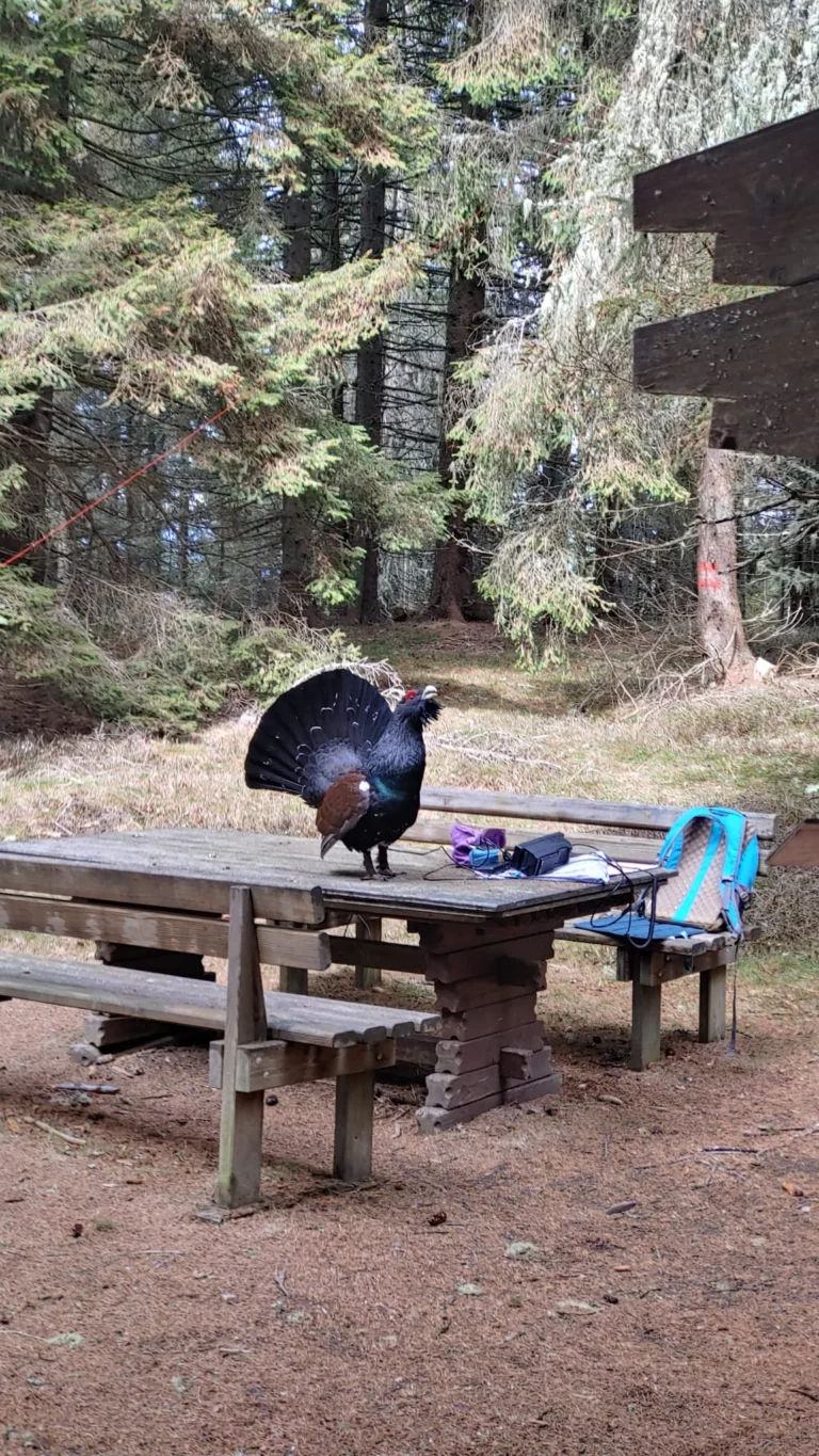
A guest post by Michael, OE5HKT. The article was written from his material (text, voice messages, photos, video) with editorial support from oeradio.at.
"I'm not sure whether this fits your blog," Michael, OE5HKT, wrote to us about his project. Does it fit? It doesn't just fit, it fits very well. Trying out new methods and using AI to build the things you have in mind is exactly what this blog is about. With the help of Claude, Michael built a Doppler tracking system for the Icom IC-705 that runs over WiFi, plus a small satellite pointer and a rotary encoder for use in the field, and tested it all via the satellite RS-44. According to him, the project was done in about a week of active work with the AI, though it had been on his mind for much longer. By his own account, he did not write a single line of source code himself, and the result works on the air.
What it is about: Doppler and an inverting transponder
Satellites in low Earth orbit move fast, so the receive frequency changes during a pass. Anyone working SSB would have to keep retuning. RS-44 (DOSAAF-85) adds a complication: it is an inverting linear transponder. You transmit on 2 m in LSB (uplink about 145.935 to 145.995 MHz) and listen on 70 cm in USB (downlink about 435.610 to 435.670 MHz), and when retuning, the two sides move in opposite directions. Doppler tracking takes this work off the operator and keeps your own signal at the desired frequency in the transponder.
The setup at a glance
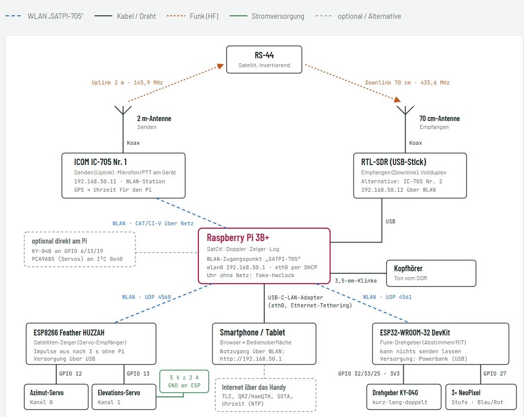
The building blocks, as the diagram shows them:
- Raspberry Pi 3B+ with the software for satellite orbit, Doppler correction, pointer control and logbook. It sets up its own WiFi network ("SATPI-705"), and you open its user interface in the browser on a smartphone or tablet. Without a network, a fake-hwclock keeps the time; in operation, the IC-705's GPS receiver supplies it.
- Icom IC-705 as the transmitter on 2 m. The Pi controls it via CAT (CI-V) over WiFi; microphone and PTT stay on the radio.
- RTL-SDR stick on the Pi for the return channel on 70 cm. This lets you monitor your own downlink in full duplex. Alternatively, a second IC-705 can be used. The Pi outputs the audio to headphones.
- Two antennas: 2 m for transmitting, 70 cm for receiving.
- Satellite pointer with an ESP8266 (Feather HUZZAH) and two servos for azimuth and elevation, driven via UDP over WiFi.
- Wireless rotary encoder with an ESP32, a rotary encoder (KY-040) for tuning or for the RIT, and three NeoPixels as a status display. It also communicates over WiFi and runs from a power bank.
- Internet via the phone, if needed, for current orbital data (TLE), callsign lookups (QRZ, HamQTH), SOTA data and the time.
The original idea was to combine everything on the Raspberry Pi. According to Michael, the very first test showed that this is impractical in the field, because everything sits in one place and you cannot move around. So the pointer and the rotary encoder became separate parts connected over WiFi.
The satellite pointer
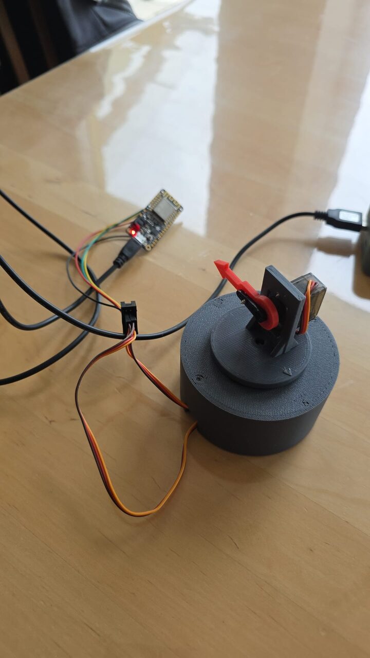
In the field, the pointer shows the direction and the height at which the satellite currently is. In Michael's experience, this helps enormously in the field, because you immediately get a feel for where the satellite is. The flight path can also be simulated in advance to see where the satellite will travel. The servo pulses switch off when nothing has come from the Pi for three seconds.
The video also shows the settings of the web interface: pulse lengths for azimuth and elevation, an option to reverse the elevation, buttons for fixed directions, and "Demonstrate" and "Follow the satellite". RS-44 (DOSAAF-85) is selected as the satellite here.
In practice: the second QSO via RS-44
There have only been two passes so far, as Michael stresses. On the first one, on Sunday, he was still off frequency, which by his account was an operating error and not a software error. It was about the downlink offset: according to him, the RS-44 downlink is shifted by about 2.4 kHz from what is expected. This offset has to be set correctly. The AI had taken it into account; Michael had simply misinterpreted it.
On the second pass, "everything already worked pretty well". On air he got 5/9 in both directions. According to the recording, the other station expressly praised the frequency tracking: it was "excellent", he was exactly on frequency.
The role of the AI
According to Michael, all of the source code comes from Claude. He described what he wanted and tested the results. One episode illustrates this well: the AI suggested programming the ESP32 modules himself in the Arduino environment. Michael preferred to simply plug everything into the Raspberry Pi and have the AI write a script that programs the modules. That worked without any problem.
For us, one point of perspective remains important: the AI delivered the code, but the whole thing proved itself through testing, measuring and on-air use, on the device and in the QSO. A mistake like the downlink offset shows that responsibility for the settings stays with the operator.
What comes next
- The rotary encoder still needs an enclosure. It switches between two modes, RIT and adjusting the frequency. Michael has not yet actively tried the RIT in satellite operation.
- The whole thing is meant to become portable, so that Michael can work via satellites from SOTA summits in the future as well.
- Michael has offered to write something about the project himself if needed.
Sources
- ARRL: Russian DOSAAF-85 (RS-44) amateur radio satellite transponder now active (frequencies and modes of the transponder)
- SatNOGS DB: DOSAAF-85 (RS-44), NORAD 44909
- All details on the setup, the tests and the QSO come from OE5HKT (text, voice messages, diagram, photos and video).
Related: Satellite Tracking and Reception for Beginners: From App to Antenna
Transparency Notice
The project described was developed by OE5HKT with the support of an AI (Claude, Anthropic). This article was written from OE5HKT's material with editorial support from AI (Claude, Anthropic): text, voice messages (transcribed with speech recognition), diagram, photos and video come from OE5HKT. The editorial team reviewed and edited all content. Photos and video are not AI images. Despite careful review, occasional inaccuracies may remain; we welcome feedback by email at [email protected].
73 – your oeradio.at editorial team