Few pieces of gear in the shack are as widely misunderstood as the matching unit. Everybody calls it an antenna tuner, and the name is the first thing that misleads: the antenna is not being tuned at all, it stays exactly as good or as bad as it was. What gets tuned is what the finals see.
This article sorts the topic out: what is inside the box, where the power actually goes, why the feedline matters more than the tuner itself, and when the manual classic beats an automatic unit. If you want the underlying matching theory first, read our article on baluns and ununs.
What a tuner does, and what it does not
A matching unit is an adjustable LC network. It transforms the complex impedance arriving at the end of the feedline into a real 50 ohms for the transceiver. The power amplifier sees a clean load, does not fold back and does not go into protection. That is the entire purpose.
What does not happen: the efficiency of the antenna is unchanged. A wire that is too short stays a wire that is too short. The mismatch between tuner and antenna remains, standing wave included. The tuner moves the place where the problem ends, it does not solve it.
The second common misconception is about the meter. SWR 1.0 at the rig is not a quality statement about your antenna system, only about the load at the transmitter output. A 50 ohm dummy load reads 1.0 as well and radiates nothing. If you want to know what the antenna is really doing, measure at the feedpoint, for example with a NanoVNA.
What is inside the box
Practically every matching unit is built from two or three adjustable components, classically a coil and a capacitor. The topology decides matching range and losses:
- L network: one coil, one capacitor. The lowest-loss arrangement, typical insertion loss around 0.1 to 0.3 dB. The drawback: it only matches in one direction, depending on whether the load is above or below 50 ohms.
- T network (CLC): two variable capacitors with a coil between them. The classic in almost every commercial manual tuner, because it matches everything from near short to near open. The price is ambiguity: there are several settings that produce SWR 1.0, and most of them are worse than the best one.
- Pi network: familiar from valve transmitters, good harmonic suppression, but it needs large capacitances on the low bands.
- Z-match: a resonant, link-coupled design with a balanced output, popular in the QRP scene and with open-wire feed because it covers several bands without switching.

Automatic tuners use the same networks, except relays switch fixed steps of capacitance and inductance. A microcontroller works through the combinations and stores the result, so the next band change needs no search run.

The price of matching
Every match costs power, and more of it than most people assume. Close to a match, a decent tuner has an insertion loss below 0.3 dB, which is negligible. Under extreme mismatch, 2 to 4 dB are possible, and then half to two thirds of your output stays in the box as heat.
The physics is quickly explained. Into a very low impedance, say 3 ohms with a substantial reactive part, the same power means four times the current compared with 50 ohms. Loss in the coil wire rises with the square of the current, so by a factor of 16. That is exactly why a tuner gets hot when it has to match a short wire on 80 metres.
The T network adds a quirk worth knowing. Because several settings produce SWR 1.0, the first dip you find is not automatically the best one. The practical rule: look for the solution that keeps the capacitances as large as possible, with at least one capacitor near its end stop. If a match is only possible with both capacitors near mid scale, tuning becomes sharp, Q goes up and dissipation rises noticeably.
The corresponding workshop test is unglamorous but effective: after a few minutes of operating, take the lid off and touch the coil. Too hot to touch means a serious part of your output is staying in the matching unit. In one comparison on a doublet with 300 ohm feeder, a built-in automatic tuner was at least 3 dB worse than the best unit in the group on four bands, which at 100 watts means at least 50 watts of heating in the shack.
The bigger lever is the feedline
Anyone discussing tuner losses while ignoring the feedline is optimising the wrong end. On a mismatched line, forward and reflected waves travel through the cable repeatedly, and every pass costs attenuation. The table below works this through for 30 metres of cable on 20 metres, based on the figures from our coax comparison:
| 30 m feedline, 14 MHz | SWR 1:1 | SWR 3:1 | SWR 5:1 | SWR 10:1 | SWR 20:1 |
|---|---|---|---|---|---|
| RG-58 | 1.5 dB | 2.1 dB | 2.9 dB | 4.5 dB | 6.6 dB |
| RG-213 | 0.5 dB | 0.9 dB | 1.2 dB | 2.1 dB | 3.5 dB |
| Ecoflex 10 | 0.4 dB | 0.7 dB | 1.0 dB | 1.7 dB | 3.0 dB |
| 450 ohm window line | 0.15 dB | 0.25 dB | 0.4 dB | 0.7 dB | 1.3 dB |
Which is the real message of this article: a tuner in the shack repairs the meter reading, not the power budget. Running a multiband antenna through a long coax feeder at high SWR wastes power no matter how good the matching unit is. Two ways lead out of it, either a matching unit right at the feedpoint or a low-loss balanced feeder. For your own numbers with different lengths and frequencies, use our Kabelblick calculator.
Manual tuners
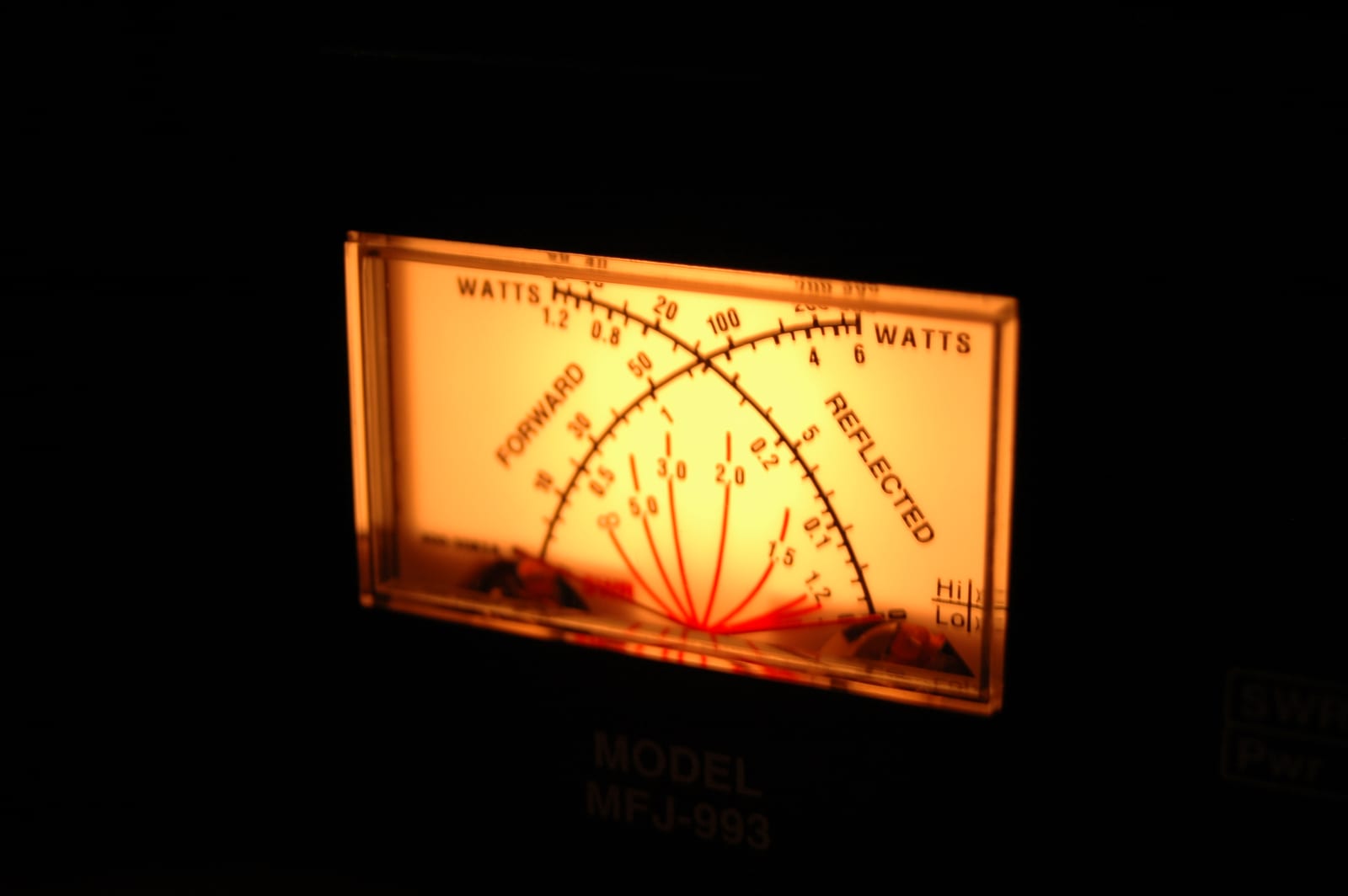
A manual tuner is an honest piece of engineering: roller inductor or tapped coil, one or two air variable capacitors, a cross-needle meter. None of it breaks, because none of it runs software.
Its strengths are high power and extreme loads. Air variables with proper plate spacing and a roller inductor of silver-plated wire handle voltages and currents that make a relay with a toroid give up long before. For a kilowatt and beyond, for open-wire feed and for antennas that sit very far from 50 ohms on individual bands, this is still the most robust solution.
The downside is the workload. Every band change means retuning, and if you change bands every ten minutes in a contest you lose time. In exchange you get something automatics do not provide: a feel for how sharp the match is and how far the antenna sits from resonance.

One buying caveat since 2024 that many recommendation lists online still miss: MFJ ended production in Starkville on 17 May 2024, taking the Ameritron, Vectronics and Mirage brands with it. The antenna brands Hy-Gain and Cushcraft went to ITU Corporation in Indiana in April 2026 and continue there, but the classic MFJ tuners are essentially a used-market item now. Buying new today means Palstar, European makers such as Annecke for balanced matching units, or homebrew.
Automatic tuners
An automatic tuner takes the knob-twiddling off your hands. It measures, switches relays, finds a solution in one to three seconds and remembers it for that frequency. For multiband operating, for digital modes with frequent band changes and for portable work, it is the more practical route.
The limits are in the physics of the parts. Toroidal inductors and small relays cap the power, typically at 100 to 200 watts, while larger external units manage a kilowatt. Then there is heat: in continuous-carrier modes such as FT8 the tuner is heating all the time, not only between overs. The popular ATU-100, based on the open-source design by N7DDC, is rated 100 watts on paper, but practice suggests keeping FT8 nearer 50 watts so the small toroids do not overheat. It uses a 7x7 network of seven switchable inductors and seven capacitors, covers 1.8 to 50 MHz and starts its search at one to five watts of drive.
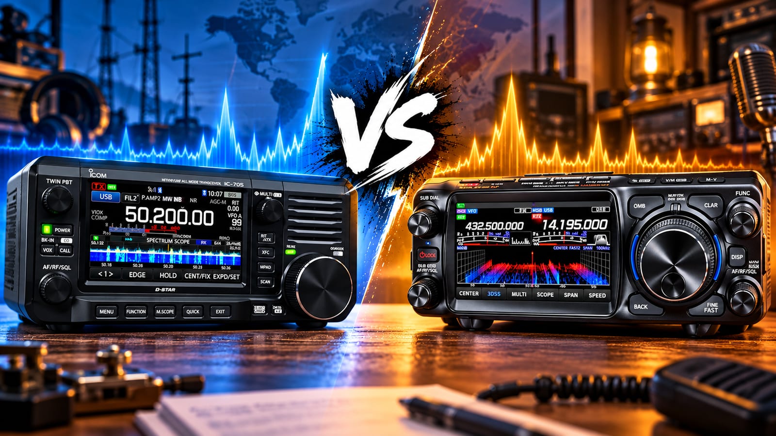
QRP has its own class of very small units. The Elecraft T1 covers 1.8 to 54 MHz, handles 20 watts SSB and CW or 10 watts in digital modes and matches loads to around 10:1 SWR, with reduced range on 160 and 6 metres. The Icom AH-705 for the IC-705 works at up to 10 watts, needs at least 30 metres of wire for 1.8 to 50 MHz or 7 metres from 3.5 MHz upwards, tunes in two to three seconds and stays below 2:1 afterwards. If you work with a handful of watts, our article on QRP operating gives the context.
Internal, external or at the feedpoint
Built-in tuners are convenient and take no space. Their catch range is deliberately small: the IC-7300 matches roughly 16.7 to 150 ohms, which is 3:1 SWR, and the FT-991A and most other rigs in that class are similar. For a resonant antenna with some bandwidth margin that is fine. For a random wire it is not. Some rigs also offer an emergency forced tuning mode that works outside the regular range, but that is not a permanent operating condition.
External tuners in the shack widen the range considerably, often to 10:1 SWR and beyond, and allow higher power. They change nothing about the loss on the line, see the table above.
Matching units at the antenna feedpoint are technically the cleanest solution. The coax runs matched, the extra loss disappears, and the matching happens where the impedance actually occurs. The Icom AH-4 and AH-705, the SGC units or a CG-3000 are built for exactly that: weatherproof housing, control over the coax, terminals for wire and counterpoise. Two things need planning, namely a proper radial system or counterpoise and enough distance from the shack. A random wire that starts right at the window reliably puts RF into your microphone, however good the tuner is. With small high-Q antennas such as a magnetic loop, the matching always sits at the antenna anyway.
Tuning it properly
- Tune at low power. Ten watts in a carrier mode is enough for any tuner. Full power into a load that is not yet matched is the most common reason for burnt relay contacts.
- Never tune through the amplifier. The PA belongs in bypass or standby while you tune. If the tuner sits behind the amplifier, it must be rated for its full output.
- Measure first, tune second. If you know the feedpoint impedance, you know in advance whether the tuner can find a low-loss solution at all.
- Keep the memories clean. After antenna changes, a new cable or a different location, clear the stored settings of an automatic tuner, otherwise it reuses an old and unsuitable solution.
- On a T network, look for the large capacitance. Do not take the first dip, take the one with the capacitors meshed as far as possible.
Videos on the topic
What suits which station
| Situation | Recommendation |
|---|---|
| Resonant mono- or multiband antenna, SWR below 3:1 | The built-in tuner is enough, often you need none at all |
| Wire antenna on many bands, frequent band changes | External automatic tuner with memories |
| Portable, QRP, minimum weight | Small auto ATU or a homebrew Z-match |
| A kilowatt and beyond | Manual tuner with roller inductor, or a QRO-class auto tuner |
| Open-wire feed and true all-band operating | Balanced matching unit, Z-match or Annecke style |
| Long coax run, high SWR on some bands | Put the matching unit at the feedpoint, not in the shack |
| FT8 and other continuous-carrier modes | Reduce power and keep an eye on tuner heating |
That is the summary, too. A tuner is no substitute for a suitable antenna, it is the tool that makes an existing antenna usable across more bands. Manual or automatic is less a matter of faith than a question of power level and convenience. The far bigger differences in the power budget happen elsewhere, in the choice of feedline and in the location of the matching. Get those right and you can pick the tuner itself to taste. How this plays out with different antenna types is covered in our article on vertical antennas.
73 – your oeradio.at team
Transparency Notice
This article was researched and written with AI assistance (Claude, Anthropic). The content was reviewed by the oeradio.at editorial team and prepared for the Austrian amateur radio community. The attenuation figures in the table are calculated from the cable data in our coax comparison. Corrections are welcome at [email protected].