Table of Contents
- Troposcatter: Scattering in the Troposphere
- The Physics of Troposcatter
- Troposcatter in Practice
- Tropo Ducting: The Big Brother
- Equipment for Troposcatter
- Digital Modes for Troposcatter
- Rain Scatter: Rain as a Reflector
- Rain Scatter in Practice
- Rain Scatter on Different Bands
- Aircraft Scatter: Reflection from Aeroplanes
- Practical Tips for Austrian Operators
- Software and Tools
- Troposcatter vs. Other VHF DX Mechanisms
- Getting Started with Troposcatter and Rain Scatter
- Transparency Notice
On VHF and UHF, range normally ends at the horizon. But the atmosphere has some tricks up its sleeve that enable radio contacts far beyond line of sight — without the ionosphere, satellites, or the Moon. Troposcatter, Rain Scatter, and Aircraft Scatter exploit physical effects in the troposphere to scatter signals over hundreds of kilometres. These propagation mechanisms are particularly fascinating for VHF/UHF DX enthusiasts because, with the right equipment and some patience, they enable astonishing distances.
Troposcatter: Scattering in the Troposphere
Troposcatter (tropospheric scattering) is a propagation mechanism in which radio signals are scattered by inhomogeneities and turbulence in the troposphere. The troposphere is the lowest layer of the Earth's atmosphere, extending from the ground to roughly 10–15 km altitude. This layer is subject to constant thermal and mechanical turbulence — different air masses collide, temperature and humidity gradients create fluctuations in the refractive index. At these boundary layers, a small fraction of radio energy is scattered and reaches the Earth's surface at distances typically ranging from 300 to 800 km.
The principle has been known since the 1950s and was used by the military for long-range communications (troposcatter links) — with enormous parabolic antennas and kilowatt transmitters. In amateur radio, troposcatter is considerably more demanding, but with modern technology and digital modes it is quite achievable.
The Physics of Troposcatter
Scattering occurs at regions where the refractive index of the air changes abruptly. Such discontinuities arise from:
- Temperature inversions: Warm air above cold air creates a sharp boundary layer. At this boundary the refractive index changes, and part of the radio energy is reflected or scattered.
- Humidity gradients: Abrupt changes in humidity — for example when dry air flows over moist air — act similarly to temperature inversions.
- Turbulent mixing: Even in apparently homogeneous air, small turbulence cells constantly vary the refractive index locally. Scattering from these cells is weak but measurable.
The scattering losses are substantial — typically 170–200 dB on a 500 km path at 144 MHz. This means signals are extremely weak. But they are there, and with the right equipment and sensitive digital modes, they can be used.
Troposcatter in Practice
Troposcatter works on all VHF and UHF bands, with the usable bands and achievable distances closely related:
- 144 MHz (2 m): The primary band for troposcatter DX in amateur radio. Ranges of 300–800 km are realistic. The lower path losses at 2 m compared to higher frequencies make this band ideal.
- 432 MHz (70 cm): Also usable, but the higher path losses require even more power and antenna gain. Ranges up to 500 km are possible with appropriate equipment.
- 1296 MHz (23 cm) and higher: Troposcatter becomes more difficult with increasing frequency, but on microwave bands other scattering effects (Rain Scatter) come into play.
The best time for troposcatter is during stable high-pressure weather, particularly near coasts and over the sea, where pronounced temperature and humidity inversions form. Warm fronts and the transitional seasons of spring and autumn often offer good conditions. For Austrian operators, paths across the plains to the north (Germany, Poland) and south (the Adriatic, Italy) are particularly interesting.
Tropo Ducting: The Big Brother
Troposcatter and tropo ducting are related but different phenomena. In ducting, a pronounced temperature inversion forms and acts as a waveguide — signals are not scattered but literally guided. The result is significantly stronger signals over greater distances (up to 2,000+ km), but ducting events are rare and unpredictable.
Typical ducting situations for Austrian operators:
- Autumn high pressure: Stable high-pressure systems in September/October with inversion layers can produce spectacular ducting openings across Central Europe
- Adriatic ducting: Warm air over the cool Adriatic creates excellent conditions for ducting on OE–I, OE–9A, OE–S5 paths
- Summer inversions: After hot days with cold nights, short-lived inversions can form
During ducting openings, signal strengths of S5–S9 over 500+ km on 2 m are not uncommon — quite unlike the weak troposcatter signal. Propagation conditions can be partially estimated using weather models and dedicated tropospheric forecasts (e.g. William Hepburn's Tropo Forecast).
Equipment for Troposcatter
Troposcatter is not a QRP pursuit — the path losses demand a serious station:
- Transmit power: 50–200 W on 2 m is the minimum. Many successful troposcatter operators run 200–400 W. More is better, as long as legal limits are respected.
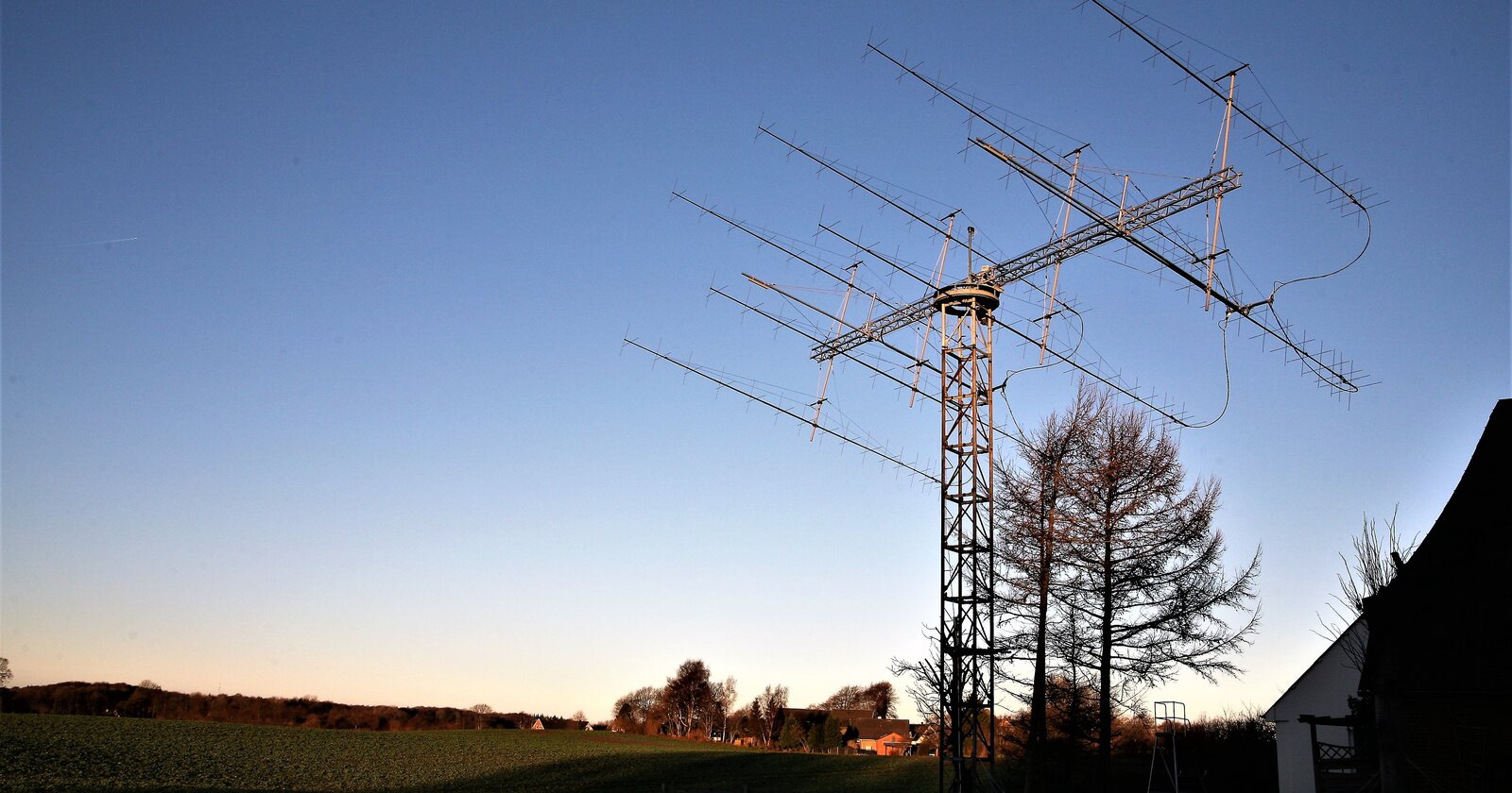
- Antennas: High gain is crucial. A single long Yagi antenna (10–16 elements on 2 m) is the minimum. Stacked Yagi arrays (2x or 4x) provide an additional 3–6 dB and can make the difference between success and failure.
- Preamplifier: A low-noise preamplifier (LNA) mounted at the mast, directly at the antenna, significantly improves reception. Noise figures below 0.5 dB are desirable.
- Coaxial cable: High-quality, low-loss cables (e.g. Ecoflex 15, Aircom Plus) are essential. On 144 MHz a long run of RG213 can cost 3–4 dB — more than doubling the transmit power would compensate.
- Transceiver: An SSB/CW-capable VHF transceiver with a stable oscillator. All-mode radios such as Icom IC-9700, Yaesu FT-991A, or classic Kenwood VHF transceivers are suitable.
Digital Modes for Troposcatter
The digital modes revolution has made troposcatter DX significantly more accessible. WSJT-X is the reference software:
- Q65: Specifically developed for troposcatter and EME. Q65 uses 65-FSK modulation and can decode signals down to -27 dB below the noise floor. Various submodes (Q65-15A through Q65-120C) are available for different propagation conditions.
- JT65: The classic weak-signal mode, also suitable for troposcatter. Increasingly being superseded by Q65.
- FT8: Works with stronger troposcatter signals but is not sensitive enough for the weakest signals (limit around -20 dB).
- CW: Remains an option for experienced operators — a trained ear can still copy CW signals below the noise floor.
- SSB: The preferred mode during stronger troposcatter signals and especially during ducting openings for fast QSOs.
On 2 m, the common frequencies are: 144.174 MHz (FT8), 144.120 MHz (Q65), 144.300 MHz (SSB calling frequency). The EME frequencies are also used for troposcatter, as the technical requirements are similar.
Rain Scatter: Rain as a Reflector
Rain Scatter is a fascinating propagation mechanism that plays a particularly important role on the microwave bands. The principle is straightforward: raindrops scatter electromagnetic waves — and the closer the wavelength approaches the droplet size, the more effective the scattering becomes.
Raindrops have typical diameters of 1–5 mm. The wavelength at 10 GHz (3 cm band) is 3 cm — only about one order of magnitude above the droplet size. On this band, Rain Scatter is particularly effective. But it also works at 5.7 GHz (6 cm), 24 GHz (1.2 cm), and even 47 GHz, where raindrops can act as scatterers.
Rain Scatter in Practice
Heavy rain cells — especially thunderstorm cells with intense precipitation — act as volumetric reflectors. The procedure:
- Identify the rain cell: Weather radar (e.g. GeoSphere Austria (formerly ZAMG), DWD, Windy.com) shows active precipitation cells in real time. Intense cells with high reflectivity values (red/purple on radar imagery) are the best scatterers.
- Point the antenna at the rain cell: Don't aim at the other station — aim at the rain cell! Both stations point their antennas at the same rain cell, which acts as a common scatterer.
- Adjust elevation: Depending on the distance to the rain cell, the antenna may need to be tilted slightly upward. Thunderstorm cells often reach 10–15 km altitude.
- Complete the QSO: The opening lasts as long as the rain cell is active — minutes to an hour. Fast operating modes are an advantage.
Typical ranges for Rain Scatter at 10 GHz: 100–300 km. This may sound modest compared to HF, but on a band where normal range is 20–30 km, it is impressive. In favourable cases, distances of 400+ km have been bridged via Rain Scatter at 10 GHz.
Rain Scatter on Different Bands
- 10 GHz (3 cm): The classic Rain Scatter band. Homebrew transverters and small parabolic dishes (60–90 cm) are sufficient. Many microwave enthusiasts start here.
- 5.7 GHz (6 cm): Rain Scatter works but is weaker than at 10 GHz. Larger antennas or more power compensate.
- 24 GHz (1.2 cm): Very effective Rain Scatter, but atmospheric attenuation by the rain itself can weaken the signal during heavy precipitation (paradox: too much rain on the path attenuates more than it scatters).
- 1296 MHz (23 cm): Rain Scatter is minimal on this band — raindrops are too small relative to the 23 cm wavelength for effective scattering.
Aircraft Scatter: Reflection from Aeroplanes
Aircraft Scatter is another atmospheric propagation mechanism that works on VHF and UHF. Aircraft — especially large commercial jets with their metal fuselage — reflect radio signals. When an aircraft flies precisely on the path between two stations, it can briefly serve as a reflector.
Characteristics of Aircraft Scatter:
- Signal duration: reflections lasting from a few seconds up to about a minute — longer than a meteor ping, with a slowly gliding Doppler shift as the aircraft crosses the path
- Signal strength: Variable — from barely audible to S3–S5, depending on aircraft size, distance and geometry
- Range: 200–600 km, depending on flight altitude (typically 10,000–12,000 m for commercial aircraft)
- Frequency: Best on 144 MHz and 432 MHz
- Predictability: Flight routes are known — websites like Flightradar24 show aircraft in real time. You can deliberately wait for aircraft crossing the desired path
Aircraft Scatter is more of a curiosity than a reliable DX mechanism, but it impressively demonstrates the diversity of propagation possibilities on VHF. For operation, fast digital modes such as MSK144 in WSJT-X are suitable (originally developed for meteor scatter); because the reflections often last longer, Q65-15 is used as well.
Practical Tips for Austrian Operators
Austria is geographically well-positioned for tropospheric DX propagation. The Alps create interesting weather dynamics, and the central location in Europe enables paths in many directions:
- Location choice: Elevated locations are ideal for troposcatter. Anyone with access to a mountain station or a high QTH benefits enormously. Many Austrian VHF/UHF repeaters are sited on mountains — this is no coincidence.
- Paths across flat terrain: The best troposcatter paths run over flat terrain. From eastern Austria northward (Vienna–Berlin, Vienna–Hamburg), the topographic conditions are favourable.
- Watch for Adriatic ducting: The Adriatic is one of Europe's best ducting regions. Austrian stations in Carinthia and Styria can reach Italian and Croatian stations with strong signals during ducting events.
- Use weather radar: For Rain Scatter on microwaves, GeoSphere Austria radar is indispensable. Thunderstorm cells over the Alpine foothills or the Pannonian Plain are ideal Rain Scatter reflectors.
- Participate in contests: VHF/UHF contests (IARU VHF Contest, Marconi VHF Contest, ÖVSV VHF activity contest) are the best opportunity to experience troposcatter and ducting — many stations are QRV simultaneously, and activity is high.
Software and Tools
For successful troposcatter and Rain Scatter DX, software tools are essential alongside radio equipment:
- WSJT-X: The indispensable software for weak signals. Q65 for troposcatter, MSK144 for aircraft scatter, FT8 as an all-rounder
- Hepburn Tropo Forecast: William Hepburn's tropospheric forecast maps show expected ducting conditions across Europe. Essential for planning VHF DX attempts
- DXMaps.com: Real-time map with VHF/UHF DX spots. Shows active propagation paths and helps identify openings
- PSK Reporter: Automatic reception reports from WSJT-X users worldwide. Shows in real time which paths are active
- Weather radar: GeoSphere Austria, DWD, Windy.com — essential for Rain Scatter planning
- Flightradar24: For aircraft scatter attempts — shows aircraft in real time on the desired path
- VOACAP Online: Primarily for HF, but the general propagation concepts aid understanding
Troposcatter vs. Other VHF DX Mechanisms
How does troposcatter compare with other VHF DX methods?
- Sporadic E: Unpredictable, but when it occurs, extremely strong signals over 800–2,300 km. Mainly on 6 m (rarely on 2 m). Seasonal (May–August).
- Meteor scatter: Reflection from ionised meteor trails. Range 1,000–2,200 km, but only fractions of a second per burst. Works year-round with MSK144.
- EME (Moonbounce): Any distance, but major equipment investment (long Yagi arrays, high power, low-noise reception).
- Troposcatter/Ducting: Always present (troposcatter) or weather-dependent (ducting). Range 300–2,000 km. Requires good equipment but not an extreme station.
- Rain Scatter: A speciality of the microwave bands. Weather-dependent but plannable via radar. Range 100–400 km at 10 GHz.
- QO-100: The geostationary amateur radio satellite provides a constant link — but via a transponder, not atmospheric effects.
Getting Started with Troposcatter and Rain Scatter
Those wishing to get into troposcatter and Rain Scatter are best starting on 2 m with troposcatter/ducting:
- Build the station: An SSB/CW-capable 2 m transceiver, a horizontal Yagi with 9+ elements, a preamplifier and low-loss cable make a good start.
- Install WSJT-X: Set up Q65 and FT8, become active on 144.174 MHz (FT8) and 144.120 MHz (Q65).
- Join VHF contests: This is where many stations are active simultaneously — the best opportunity for first troposcatter QSOs.
- Monitor tropo forecasts: Hepburn maps show when elevated tropo activity is expected.
- For Rain Scatter: A 10 GHz transverter with a small parabolic dish opens the door to a fascinating niche. Homebrew projects are well documented in the microwave community.
The combination of physics, weather, and radio technology makes troposcatter and Rain Scatter particularly captivating aspects of amateur radio. Every successful contact is a small triumph — because you have used the atmosphere itself as your antenna.
73 – your oeradio.at editorial team
Transparency Notice
This article was researched and written with the assistance of AI (Claude, Anthropic). The editorial team has reviewed and edited all content. Despite careful review, occasional inaccuracies may occur — we welcome corrections via email to [email protected]. Title image: VHF antenna array by DK5LA, photo by Reinhard Kuehn, Wikimedia Commons, CC BY-SA 4.0.