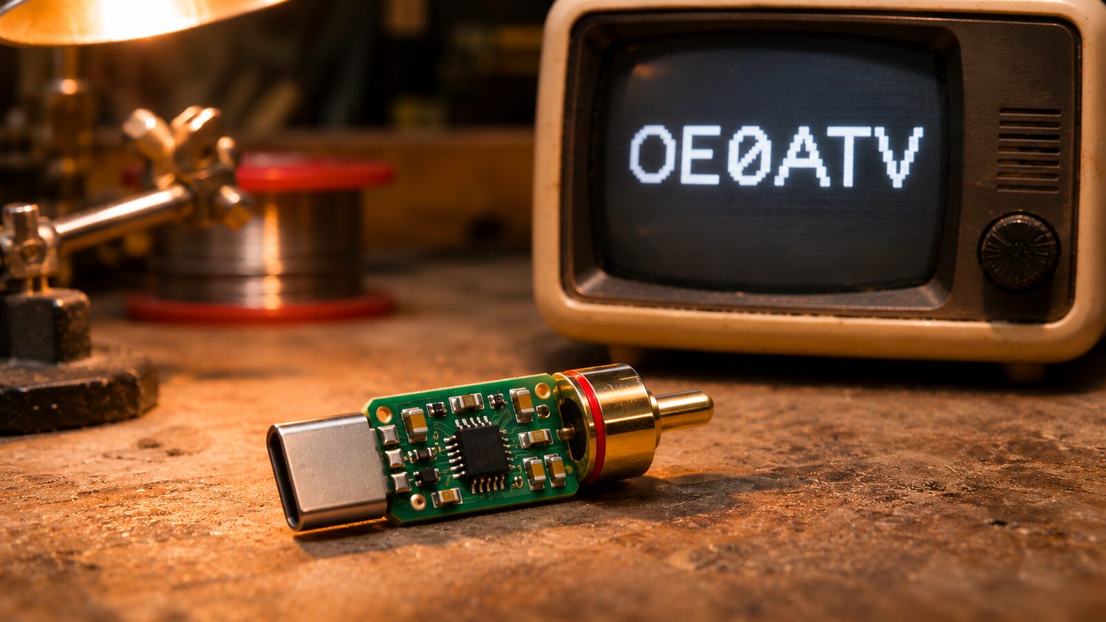
The most important thing first: the YouTuber bitluni has built a tiny board that registers as a USB device and outputs text as a composite video signal to a TV. For radio amateurs this is not a ready-made solution, but a nice inspiration for amateur radio television (ATV). Whether it is suitable for that has not been tested by anyone so far.
What bitluni built
In the video “I made a USB GPU for 20¢” (21 November 2026, length 19:52), bitluni uses a microcontroller from WCH's CH570 series. According to the datasheet, the series has a RISC-V core with up to 100 MHz, 12 KB SRAM, 240 KB code flash, USB 2.0 and a 2.4 GHz transceiver with GFSK modulation. CNX Software gives a price of around 10 cents for the CH570. The schematic in the repository, however, lists the CH572D variant in the QFN20 package, the sibling with Bluetooth LE. So if you build one yourself, look closely at which chip is on the board.
The video signal comes from the PWM output, which works here as a simple digital-to-analog converter. It is fed the line data via DMA, so the CPU does not have to output every pixel itself. The firmware in the repository generates a black-and-white PAL signal with text display. On USB, the device registers as a serial interface (CDC): whatever you send to it appears on the screen, and Ctrl+L clears the picture. According to the video, it is about 37 by 34 characters with an 8x8 character set and 11 gray levels.
One stumbling block that bitluni describes: the program code has to run from the fast RAM, because the flash is connected over SPI and is much slower. The compiler also replaces some loops with memset, and that function lives in flash. In the source code you can recognize this by the functions marked with __HIGH_CODE.
The board: connectors made of copper traces
The clever part is the mechanics. The USB-C plug and the RCA plug are formed directly from the circuit board, without any purchased connectors. In the schematic, next to the controller there are an SMD crystal (according to the datasheet a 32 MHz type), a 3.3 V regulator, a few capacitors and resistors in 0402 and a small button for programming mode. According to the video, the material costs are about 20 cents. The parts list below follows the schematic.
We did not find a license file in the repository (as of 22 November 2026). If you want to share or modify the files, it is best to ask the author.
The idea: an ID generator for ATV
In amateur radio television, the call sign is usually transmitted as an overlay in the picture. A controller that delivers text as a video signal and is controlled over USB or UART could be an exciting building block for this: call sign, locator or status messages as text.
This is expressly an inspiration. Nobody has tested it, not even bitluni. What you would have to consider:
- Levels: Composite video nominally expects about 1 V peak-to-peak into 75 ohms. You should check the level and DC component of the board with an oscilloscope and adjust them if necessary.
- Overlaying instead of replacing: The board generates its own sync pulses. A text overlay on top of a camera picture would need synchronization or a video mixer. As a test pattern or still image during breaks without a camera, it would be simpler.
- Filter: The PWM signal contains harmonics. A low-pass filter in front of the modulator makes sense.
- Modulator: The actual transmitter, for example FM ATV on 23 or 13 cm, remains a normal ATV device.
- Color: Still missing. In the video, bitluni points out that when overclocked to 150 MHz with an SPI divider of 4, the SPI clock almost exactly hits the PAL color subcarrier of 4.43 MHz (PAL basics). That is outside the chip's specification and has not been implemented. In the code there is the function
SetSysClock150MHzfor it.
On the frequencies: according to the IARU Region 1 band plan (VHF Handbook 10.03), analog ATV in the range 430 to 440 MHz has no longer been provided for since 1 January 2021. On 23 cm, ATV and digital ATV are listed, among others, at 1243.25 to 1260 MHz and 1272 to 1290.994 MHz, on 13 cm at 2322 to 2355 MHz and 2370 to 2392 MHz as well as at 2427 to 2443 MHz, as long as no satellite is operating there. National rules may differ, so please check before building.
When the breadboard becomes a transmitter
From about 16:39 in the video, bitluni reports that his CRT television also received the PWM signal over the antenna. A jumper wire on the breadboard was enough as an antenna. According to bitluni, the signal arrived as a subharmonic in VHF Band III, but the picture did not lock. That is technically plausible: a rapidly switched square-wave signal contains many harmonics, and a wire attached to it radiates some of them.
For us this means two things. First, a vivid example of the unintended spurious emissions of cheap electronics that we notice at the receiver. Second, it is no free pass: under Section 28 of the Telecommunications Act 2021, setting up and operating a radio installation is only permitted within the framework of an ordinance, a notification or a license. The making available of radio equipment is regulated by the Radio Equipment Market Surveillance Act (FMaG 2016). A setup deliberately operated as a transmitter outside the amateur radio bands is therefore not acceptable. How an experiment with unintentional radiation is to be classified legally, we have not examined. In case of doubt, ask the telecommunications authority.
The topic is not new. In 2016, Charles Lohr showed with his project Channel3 (GitHub) how an ESP8266 radiates an NTSC signal directly onto TV channel 3 via the I2S bus. There too, it is pointed out that this is not permitted in the broadcast bands without authorization.
The chip as a basis for tinkering
According to the datasheet, the CH570 has a 2.4 GHz radio module with GFSK, up to +7.5 dBm transmit power and -95 dBm sensitivity, plus USB. That makes it a very cheap basis for radio experiments in the 2.4 GHz range, for example for sensor nodes. Bluetooth is only available on the CH572 variant. Whether anyone is already building amateur radio projects with the chip is not known to us.
Parts list
The list follows the schematic in the repository. The repository contains no bill of materials with prices. We have only entered prices where there is a source.
| Component | Value / type | Approx. price | Source |
|---|---|---|---|
| U1 microcontroller | CH572D (CH570 according to the video), QFN20 | approx. 10 cents (CH570) | Schematic, CNX Software |
| Y1 crystal | SMD 3225, 4 pin, 32 MHz according to the datasheet | approx. 3 cents according to the video | Schematic, datasheet, video |
| U3 voltage regulator | ME6211C33M5G-N, SOT-23-5 | not stated | Schematic |
| C1, C3 | 2.2 µF, 0402 | not stated | Schematic |
| C2 | 100 nF, 0402 | not stated | Schematic |
| R1, R2, R7 | 5.1 kΩ, 0402 | not stated | Schematic |
| R3 | 180 Ω, 0402 | not stated | Schematic |
| R4 | 1.5 kΩ, 0402 | not stated | Schematic |
| R5 | 0 Ω, 0402 | not stated | Schematic |
| R6, R8, C4 | Value not entered in the schematic | not stated | Schematic |
| SW1 | Mini button for programming mode | not stated | Schematic |
| Board | USB-C and RCA plug as copper traces | Total material approx. 20 cents according to the video | Video |
Sources
- Video: bitluni, I made a USB GPU for 20¢
- Project files: github.com/bitluni/CH570Composite
- Datasheet CH572/CH570 (V1.1): PDF, manufacturer page: openwch/ch570
- CNX Software on the CH570/CH572
- Channel3: Hackaday, Instructables, GitHub
- IARU Region 1 VHF Handbook 10.03
- PAL (Wikipedia)
- TKG 2021 in the RIS, FMaG 2016
Best regards, Ferdl
Transparency note
I wrote and checked this article with the support of AI (Claude, Anthropic) based on the video description, the public GitHub repository, the WCH datasheet and the linked sources. We have not built the circuit ourselves and have not analyzed the video frame by frame. Information that appears only in the video is marked as such. The title image is AI-generated and shows no real board. The information corresponds to the status of 22 November 2026 and may change.