Table of Contents
- How Does a Yagi Antenna Work?
- Yagi Basics: Gain, Front-to-Back Ratio, and Bandwidth
- Yagi Designs for Different Bands
- Building a 2 m Yagi
- Popular Designs to Replicate
- Calculation and Simulation
- Tuning and Measurement with NanoVNA
- Mounting and Rotators
- Stacking: Combining Multiple Yagis
- Applications
- Building Tips
- Transparency Notice
The Yagi-Uda antenna — usually just called “Yagi” — is the most widely used directional antenna in amateur radio. It focuses energy in one direction, increases gain and range, and suppresses interference from the sides and rear. Whether for Sporadic E on 6 m and 2 m, EME experiments, or everyday repeater operation — the Yagi is the workhorse of VHF/UHF operators.

How Does a Yagi Antenna Work?
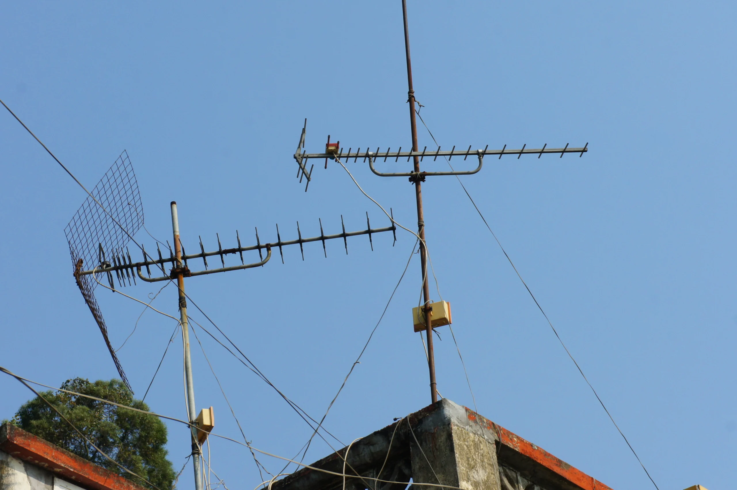
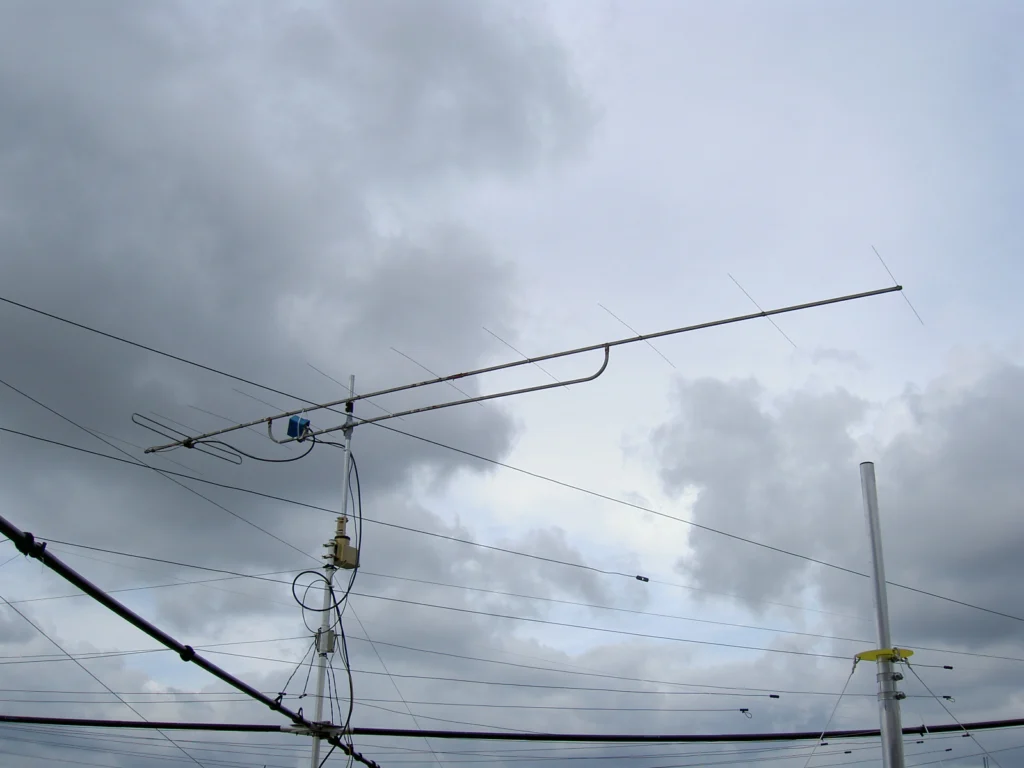
A Yagi consists of at least three elements on a common support (boom):
- Reflector: An element behind the driven element, slightly longer than a half wavelength. It reflects energy forward and improves the front-to-back ratio.
- Driven element (dipole): The only element directly connected to the coaxial cable. Its length is approximately one half wavelength.
- Directors: One or more shorter elements in front of the driven element. They direct energy forward and increase gain. More directors mean narrower beamwidth and higher gain — but also a longer boom.
The principle is based on mutual coupling: reflector and directors are not electrically connected but are excited by the electromagnetic field of the driven element (parasitic elements). Through their length and spacing, they create constructive interference in the forward direction and destructive interference to the rear.
This FDTD simulation video beautifully shows how the electromagnetic field is shaped and focused by the Yagi elements:
Yagi Basics: Gain, Front-to-Back Ratio, and Bandwidth
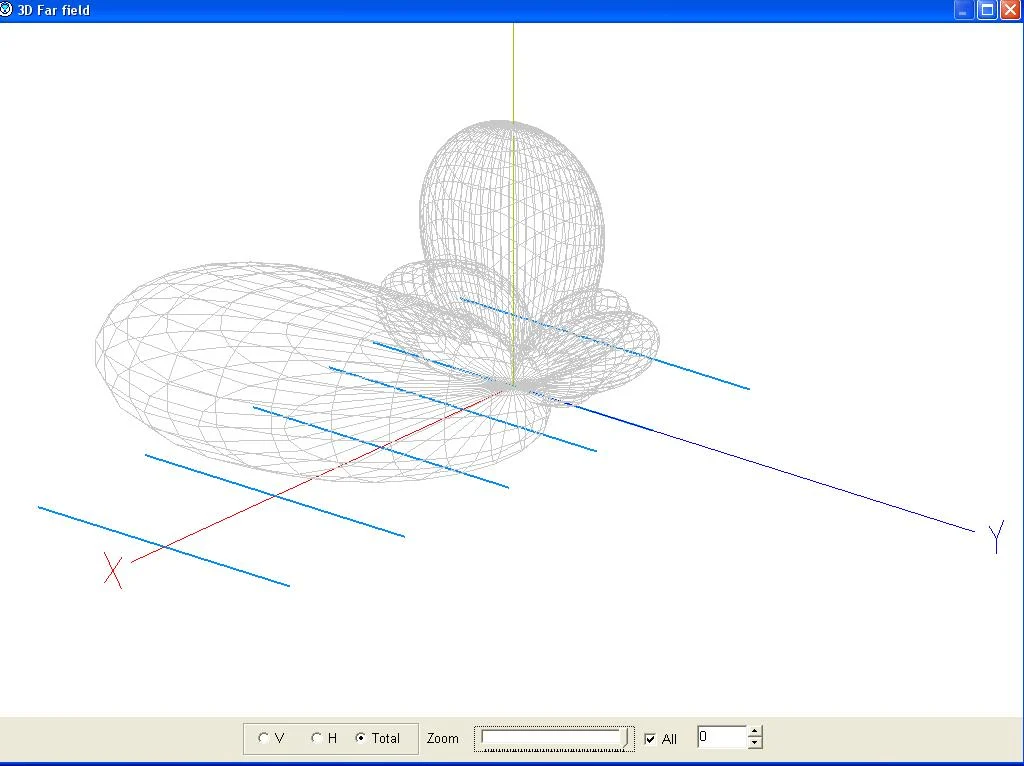
- Gain: Expressed in dBd (over dipole) or dBi (over isotropic). A 3-element Yagi provides about 6–8 dBd (depending on boom length and design), a 10-element Yagi about 12 dBd.
- Front-to-back ratio (F/B): Indicates how much rear signals are suppressed. 20 dB F/B means rear signals are 100 times weaker than forward signals.
- Bandwidth: A Yagi is inherently narrowband. More elements mean narrower bandwidth.
- Impedance: At the feed point, impedance varies by design — typically 25–50 ohms. Gamma match, hairpin match, or T-match networks are commonly used for 50-ohm coax.
Yagi Designs for Different Bands
6 m (50 MHz): Elements are about 3 m long. A 3-element Yagi for 50 MHz has a boom of about 2–3 m (depending on design) and offers about 6–8 dBd gain. Ideal for Sporadic E in summer.
2 m (144 MHz): The most popular band for Yagi antennas. A 5-element Yagi (1.8 m boom, ~9 dBd) is a good all-rounder; a 9-element (4 m boom, ~12–13 dBd) for contests and Sporadic E; long Yagis with 14+ elements (6–10 m boom, 14+ dBd) for EME and serious DX.
70 cm (432 MHz): Elements are only about 35 cm long — compact antennas with high gain are possible. A 12-element Yagi for 432 MHz has a boom of only 2 m and achieves about 13–14 dBd. For EME, arrays of 4 or more Yagis are commonly used.
Building a 2 m Yagi
Building a Yagi antenna is a rewarding project requiring minimal materials:
- Boom: Aluminium square tube (20×20 or 25×25 mm) or wooden batten (insulates the boom from the elements)
- Elements: Aluminium rod (6–10 mm diameter). Available at hardware stores as welding rod or aluminium bar
- Element mounts: Insulated bushings or 3D-printed holders — especially important with aluminium booms to insulate the driven element
- Coax cable: RG-58 or RG-213, depending on cable length and desired loss
- Matching network: Gamma match, hairpin match, or DK7ZB match for 50-ohm matching
Popular Designs to Replicate
- DK7ZB Yagis: Martin Steyer DK7ZB has published an extensive collection of optimised Yagi designs — from 3 to 17 elements, all with 28-ohm matching via a simple quarter-wave coaxial transformer (two parallel 75-ohm cables).
- G0KSC LFA/OWA Yagis: Justin Johnson G0KSC offers optimised “Low Noise Yagi” (LFA) and “Optimised Wideband Antenna” (OWA) designs — particularly low-noise and broadband.
- WA5VJB Cheap Yagi: Kent Britain WA5VJB demonstrates how to build a functional Yagi with wooden battens and welding rod for a few euros — the perfect beginner project.
This German-language video shows step-by-step how to build a solid 2 m Yagi based on the DK7ZB design with hairpin match:
Calculation and Simulation
Before building, the antenna should be simulated on computer using MMANA-GAL (free, easy to use), 4nec2 (more powerful NEC2-based simulator), or EZNEC (formerly commercial, free since 2022 after developer Roy Lewallen W7EL retired).
Tuning and Measurement with NanoVNA
After building, the antenna must be tuned. The NanoVNA is the ideal tool: measure SWR across the desired frequency range, find the resonance frequency, adjust element lengths as needed, verify impedance at the feed point, and aim for SWR below 1.5:1 in the desired range.
This excellent tutorial by w2aew shows how to use the NanoVNA to sweep an antenna and optimise its SWR:
Mounting and Rotators
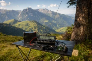
A Yagi antenna only points in one direction — for flexible operation, you need an antenna rotator. Light rotators (Yaesu G-450C, Hy-Gain HAM-IV) suit single VHF Yagis; heavy rotators (Yaesu G-2800DXA) for large arrays. For satellite operation and EME, an elevation rotator is also needed. For portable use at SOTA or contests, a photo tripod suffices.
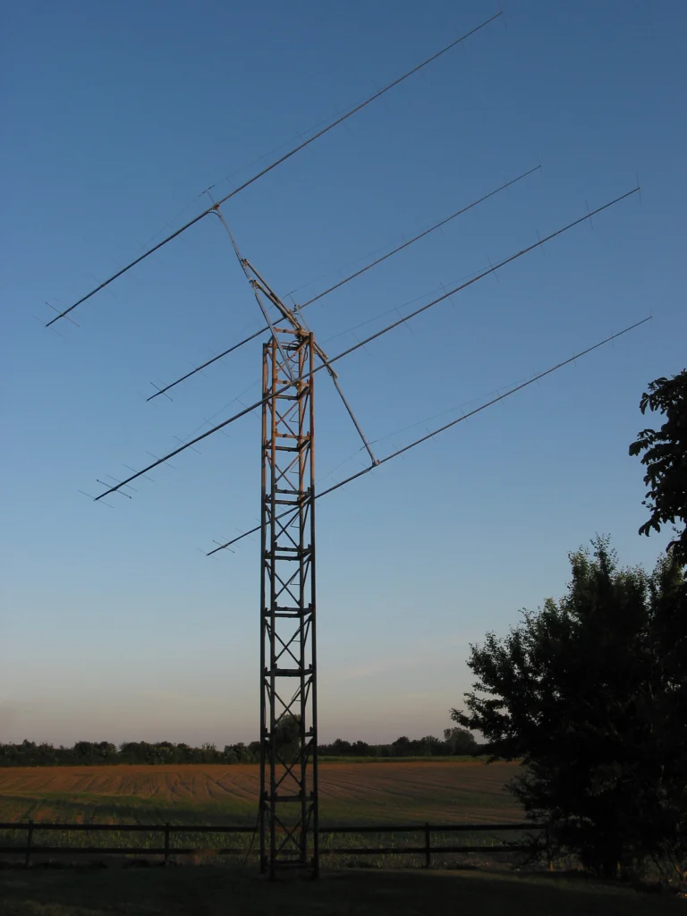
Stacking: Combining Multiple Yagis
By “stacking” — mounting two or more identical Yagis above each other or side by side — gain can theoretically be increased by up to 3 dB per doubling (in practice about 2.5–2.9 dB due to feed losses). A 2-stack provides about 3 dB more gain than a single Yagi — equivalent to doubling the effective transmit power. The Yagis must be fed in-phase and the spacing must match the design.
Applications
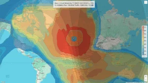
- Sporadic E and tropo DX: The Yagi focuses the signal for DX contacts on 2 m and 6 m impossible with an omnidirectional antenna
- EME (Moonbounce): Arrays of 4–16 Yagis with 20–30 dBd combined gain for EME
- Satellite reception: Cross-polarised Yagis for amateur satellite operation
- Contests: Mandatory for VHF/UHF contests — gain and directivity determine the score
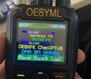
- Repeater access: A small Yagi can solve access to distant repeaters
This video demonstrates that EME (Earth-Moon-Earth) is possible from your own backyard with a single 70 cm Yagi:
Building Tips
- Precision matters: At VHF/UHF, every millimetre counts. Follow element lengths and spacings exactly.
- Aluminium, not steel: Aluminium elements are lightweight, corrosion-resistant, and have good conductivity.
- Insulated boom: With an aluminium boom, elements must be insulated — or use a wood/fibreglass boom.
- Weatherproofing: Protect coax connectors and matching networks with self-amalgamating tape or heat shrink.
- Measure, don’t guess: Use a NanoVNA to measure and tune the finished antenna.
The Yagi antenna is one of the most rewarding homebrew projects in amateur radio. With simple materials, a good design, and careful execution, you can build an antenna that matches commercial products — for a fraction of the cost. Whether as a first directional antenna for the Sporadic E season or an EME array — the Yagi remains the foundation of VHF/UHF amateur radio.
73 – your oeradio.at editorial team
Transparency Notice
This article was researched and written with the assistance of AI (Claude, Anthropic). Any illustrations used were generated with AI (ChatGPT/DALL·E, OpenAI) unless otherwise noted. The editorial team has reviewed and edited all content. Despite careful review, occasional inaccuracies may occur — we welcome corrections via email to [email protected].