
EME – Earth-Moon-Earth: When the Moon Becomes a Reflector
Imagine sending a radio signal from Earth to the Moon and receiving the echo back – a round-trip distance of approximately 768,000 kilometers. This is exactly what EME, also known as Moonbounce, is all about. This fascinating mode is one of the most challenging yet rewarding endeavors in amateur radio. In this article, we explore the fundamentals, technology, and how to get started with Earth-Moon-Earth communication on the 2 m and 70 cm bands.
What is EME?
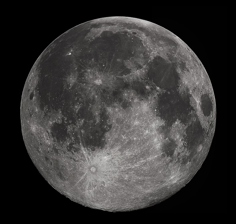
EME stands for Earth-Moon-Earth and describes a radio link where the Moon serves as a passive reflector. The signal is transmitted from an amateur radio station to the lunar surface, reflected there, and received by another station (or the same one) back on Earth. The lunar surface reflects electromagnetic waves in the VHF and UHF range, although only a tiny fraction of the energy returns.
The idea of using the Moon as a reflector dates back to the 1940s, when the US military first received radar echoes from the Moon in Project Diana in 1946. In amateur radio, the first successful EME contact was made in 1960 between stations W1BU and W6HB on 1296 MHz. Since then, EME has developed into an established, albeit demanding, operating mode.

The Physics Behind Moonbounce
The greatest challenge in EME is the enormous path loss. The signal must travel approximately 384,400 km to the Moon and the same distance back. The free-space path loss amounts to about 252 dB at 144 MHz and approximately 262 dB at 432 MHz. This means that only a vanishingly small fraction of the transmitted energy arrives back at the receiving station.
Two important propagation effects influence EME signals:
- Faraday Rotation: As the signal passes through the ionosphere, its polarization plane is rotated. This can cause a horizontally polarized signal to arrive vertically polarized at the receiving station – making it undetectable. Faraday rotation varies with time of day, season, and solar activity. Many experienced EME operators therefore use circularly polarized antennas or can rotate their antenna polarization.
- Libration Fading: The Moon is not a smooth mirror but a rough surface with mountains and craters. The signal is reflected from various points on the lunar surface. These partial reflections reach the receiving station via slightly different paths and interfere with each other, producing characteristic rapid signal fading. On 432 MHz, this effect is more pronounced than on 144 MHz.
The signal travel time is approximately 2.5 seconds for the round trip to the Moon. This echo delay is clearly audible during EME operation and is an unmistakable characteristic of this mode.
The Digital Revolution: WSJT-X and New Possibilities
Until the 2000s, EME was almost exclusively done in CW (Morse telegraphy) and required enormous antenna arrays and high transmit power. The development of specialized digital modes by Joe Taylor, K1JT, fundamentally changed EME and made it accessible to far more radio amateurs.
The WSJT-X software offers several modes specifically optimized for EME:
- JT65: The classic EME mode, developed by K1JT. JT65 uses 65-tone frequency shift keying (65-FSK) and employs strong forward error correction (Reed-Solomon code). A QSO consists of structured messages sent and received in 60-second intervals. JT65 can decode signals up to 25 dB below the noise floor.
- Q65: The more modern successor to JT65, also developed by K1JT. Q65 offers various sub-modes (Q65A through Q65E) with different symbol rates optimized for different propagation conditions. Q65 is particularly effective with strong libration fading on 432 MHz and higher bands.
- QRA64: Another EME mode based on the QRA code, enabling even more sensitive decoding than JT65. QRA64 is primarily used on the higher microwave bands.
Equipment for EME on 2 m (144 MHz)


The 2 m band is the most popular band for EME beginners, as the path loss is lower than on higher bands and antenna technology remains manageable. Typical 144 MHz EME equipment includes:
- Antenna: At minimum, a long Yagi antenna with 10 dBd or more gain. A single 9-element Yagi with approximately 13 dBd gain is a good starting point for digital EME.
- Rotor: An azimuth-elevation rotor system is essential for tracking the Moon across the sky.
- Power Amplifier: For digital modes on 2 m, 100 to 400 watts is a good starting point. For CW EME, at least 500 watts are recommended.
- Low Noise Amplifier (LNA): A low-noise preamplifier mounted directly at the antenna is indispensable. The noise figure should be below 0.5 dB, ideally 0.2 to 0.3 dB.
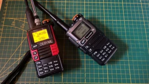
- Transceiver: A stable VHF transceiver with good frequency stability, such as the IC-9700.
- Software: WSJT-X is the standard software for EME operation.
The standard EME frequency on 2 m is 144.120 MHz for JT65B and Q65. CW EME typically takes place between 144.000 and 144.100 MHz.
EME on 70 cm (432 MHz)
The 70 cm band also offers excellent EME opportunities but places higher demands on equipment. The path loss is approximately 10 dB higher than on 2 m, which must be compensated by more antenna gain and/or higher transmit power. A typical beginner setup consists of 4 Yagis with 21 to 28 elements each, or alternatively a parabolic dish with 2 to 3 meters diameter. At least 200 to 400 watts are needed for digital modes. The standard EME frequency on 70 cm is 432.065 MHz. Q65C or Q65D are recommended modes due to stronger libration fading.

EME Contests and Activity Days
The EME community regularly organizes contests and activity weekends that facilitate getting started and increase activity levels:
- ARRL EME Contest: The largest EME competition, organized by the American Radio Relay League, held annually on multiple weekends separated by band.
- Dubus EME Contest: A European EME competition organized by Dubus magazine, particularly popular in Europe.
- Activity Weekends: On specific weekends, EME enthusiasts meet for coordinated activities, announced on ping-jockey.net.
Getting Started with Modest Equipment
Many radio amateurs believe that EME is only possible with huge antenna farms and kilowatt amplifiers. Thanks to modern digital modes, getting started today is possible with relatively modest equipment. A realistic 2 m EME starter setup includes a single long Yagi antenna (~13 dBd), an azimuth-elevation rotor, a mast-mounted LNA (NF < 0.5 dB), a VHF transceiver, a 150 to 300 watt amplifier, WSJT-X with accurate time synchronization, and low-loss coaxial cable. With patience, digital EME QSOs with larger stations are quite achievable.
Current EME Activity and Resources
The EME community is active worldwide. Key resources include ping-jockey.net for real-time EME coordination, the N0UK EME Newsletter, the WSJT-X website, Dubus magazine, and the HB9Q EME Logger. EME remains one of the most fascinating modes in amateur radio – the thought that your signal touches the Moon and returns is a thrilling experience for any radio amateur.
Videos: EME in Practice
The following videos show EME operation in practice – from contest activities to moonbounce experiments on various bands:
ARRL EME Contest 2024 – Deep Space Exploration Society (DSES)
Highlights from the second weekend of the 2024 ARRL EME Contest at the Deep Space Exploration Society in Colorado, USA. DSES operates an impressive 60-foot parabolic dish for EME contacts.
DUBUS EME Contest 2024
Coverage of the 2024 DUBUS EME Contest, Europe’s premier EME competition. Video by Mike K0FYR (Ham-Solo).
Moonbounce on 10 GHz – Ham Radio DX (VK7HH)
Hayden, VK7HH, demonstrates a moonbounce attempt on 10 GHz using a parabolic dish – a particularly challenging EME variant on microwave frequencies.
Sources and Further Reading
- Wikipedia: Earth-Moon-Earth Communication – Overview of EME history and physics
- WSJT-X Software – Official website of K1JT’s (Joe Taylor) WSJT-X software
- EA6VQ – Moon Bounce (EME) Information – Comprehensive EME resources and real-time data
- EA6VQ – Get Ready for 2m Moonbounce – Getting started guide for EME on 144 MHz with JT65B
- RSGB – Moonbounce (EME) – Technical information from the Radio Society of Great Britain
- ARRL – Weak Signal / EME – EME resources from the American Radio Relay League
- Deep Space Exploration Society – EME – EME projects and contest reports from DSES
- Electronics Notes: EME Propagation – Technical fundamentals of moonbounce propagation
- VU2NSB: EME Moonbounce Communication – Detailed technical analysis of EME contacts
73 – your oeradio.at editorial team
Transparency Notice
This article was researched and written with the assistance of AI (Claude, Anthropic). Any illustrations used were generated with AI (ChatGPT/DALL·E, OpenAI) unless otherwise noted. All content has been editorially reviewed.
