
In this article I describe the construction of a sturdy and powerful dipole antenna for the 80-metre band, specifically optimised for operation on 3.7 MHz in the SSB range. With good materials and precise tuning, a stable antenna was created that works excellently for radio connections across Europe.
Materials and Tools
- Antenna wire: DX Wire FL – 170m spool
I chose this reinforced wire because, unlike conventional copper wire, it does not stretch under tension. This makes it particularly durable and stable. (Thanks to @oe8yml) - Vector analyser: NanoVNA-H4 Vector Analyser
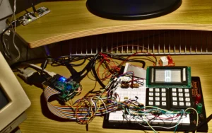
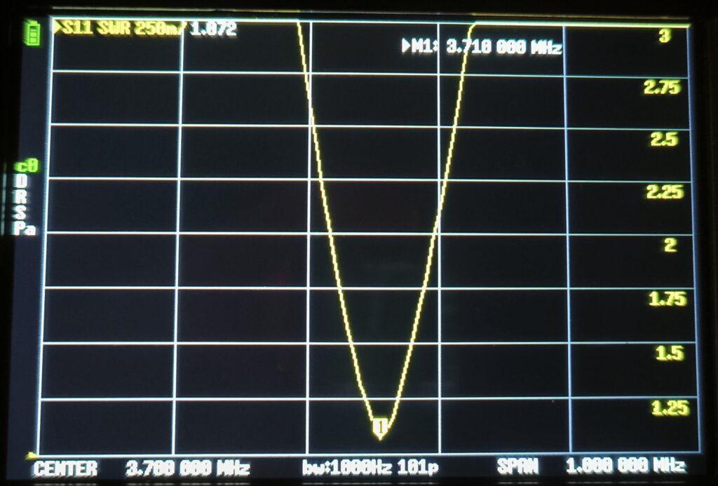
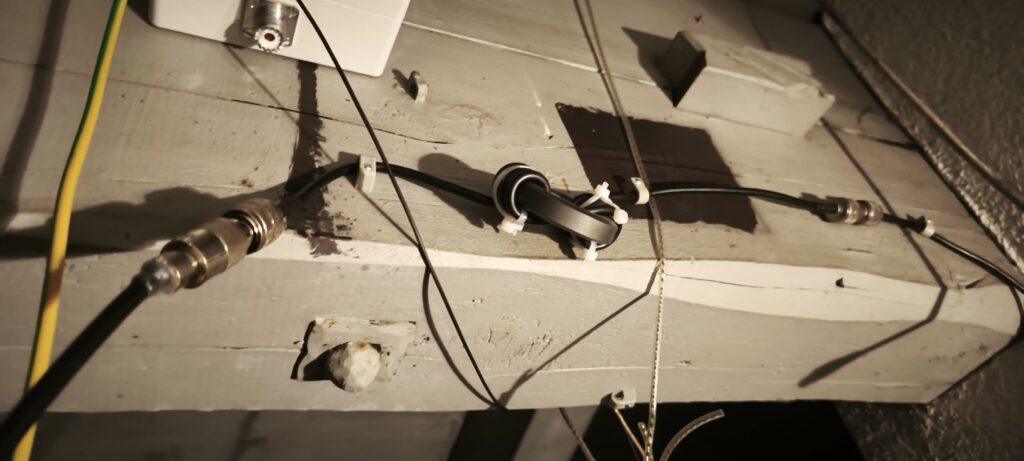
Using this analyser I was able to tune the antenna to the desired resonant frequency and perform SWR measurements. The diagram shows the measured values (see below). - Balun: 1:1 HamKing BU-200
- Common-mode choke: To avoid common-mode interference, I built a choke by winding the coaxial cable several times around a ferrite core. A clear tutorial can be found in this video.
Calculation and Length of the Dipole Elements
Using a dipole calculator I determined the ideal length for the dipole elements. The frequency of 3.7 MHz was important to me as I predominantly operate in this range (SSB). The calculated element length for a half-wave dipole was 19.277 metres.
To allow some margin for attachment and strain relief, I extended the elements to 20.2 metres.
Important: Dipole antennas should generally not be cut shorter but rather folded back at the end and then secured. This method has proven itself after I once cut an antenna too short and the SWR was far too high as a result.
Additionally, the antenna can then be adjusted to a new environment if hung somewhere else.
Tuning and Measurements
After assembly I tested the antenna using the vector analyser and found good resonance and low SWR in the 3.7 MHz range. The SWR graph shows the well-tuned resonant frequency.
We repeatedly adjusted the length by increasing or decreasing the folded-back DX Wire.
The vector analyser was placed in the middle and with 2 mobile phones (WhatsApp video call) I could see the analyser results.
With 2 PMR radios we stayed in contact and re-tensioned the antenna after each length adjustment for a new measurement.
Finally, we symmetrised the antenna (made both elements equal length).
For this I measured the length of the folded part on my colleague’s side (from the end of the loop where the twine is attached to the end of the cable), which was 90 cm.
Then I adjusted the other element accordingly.
It is important to note that an insulator should also be used during measurement (in my case twine) so as not to distort the measurement result.
Assembly and Mounting
Element Ends
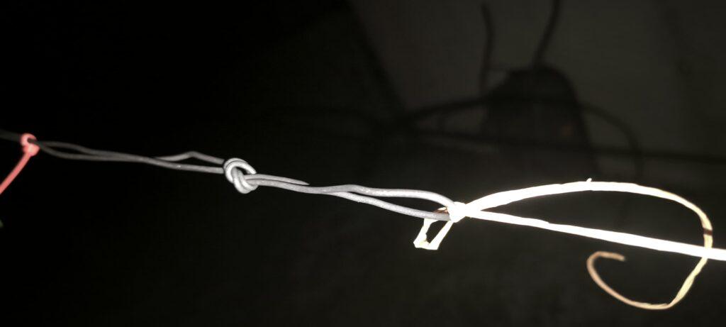
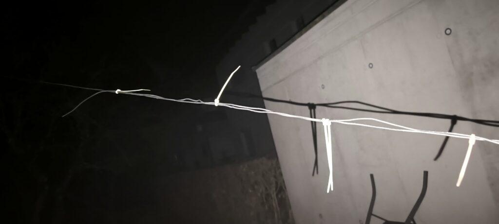
At the ends of the elements we made a loop to tie them off and absorb tensile loads. The excess wire ends were folded back and secured with cable ties.
The element ends were then attached to a tree and a fence using ordinary twine as an insulator.
Common-Mode Choke
I wound the coaxial cable several times around a ferrite core to suppress common-mode currents.
Roof Mounting
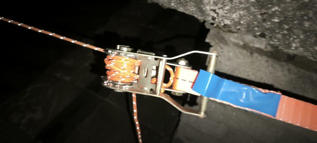
The antenna is attached to a rope that I stretched between my chimney and a tall tree in the garden. The assembly was tightened using a ratchet strap tensioner, which is also excellent for tensioning a rope. I doubled the rope (as a loop) to create more friction.
Strain Relief
Normally it is recommended to add strain relief (easily done with a pulley and a weight).
In my case I omitted this and did not tension the rope completely tight, so it should not break even if the tree moves in a storm.
Shape and Height
The antenna is strung in an inverted-V configuration.
The rope and thus the balun is approximately 8 metres high and the elements are attached at approximately 1 metre height.
Because the antenna hangs relatively low compared to the band, it radiates at a very steep angle (NVIS). This has the advantage of better communication in the near range.
Performance and Range
To test the range, I checked the antenna on PSKreporter, using a transmit power of 100W (at around 10 pm). After just two minutes of operation I could confirm an impressive range, indicating good tuning and efficiency.

Eliminating Interference
Most interference typically comes from man-made sources.
Sources of Interference
- Switch-mode power supplies (phone chargers) or other power supplies
- LEDs
A good method to roughly determine whether the interference comes from your own house is to switch off the RCD (residual current device) and power the radio from a car battery. This way you can immediately see how much interference has disappeared.
Then you can work through the individual circuit breakers room by room and quickly find the source(s).
I hope this guide and the pictures provide a good overview of building an 80-metre dipole and are useful to fellow radio amateurs. In practice, the antenna shows excellent stability and performance.