
This project article describes step by step the construction of a sheath wave indicator that shows directly on the coaxial cable whether sheath waves are being generated. When sheath waves occur, an LED lights up.
The idea for this project originally came from Heinz, DL8MH, who presented it in one of his YouTube videos. This concept inspired Michael OE8YML to develop and deploy his own version.
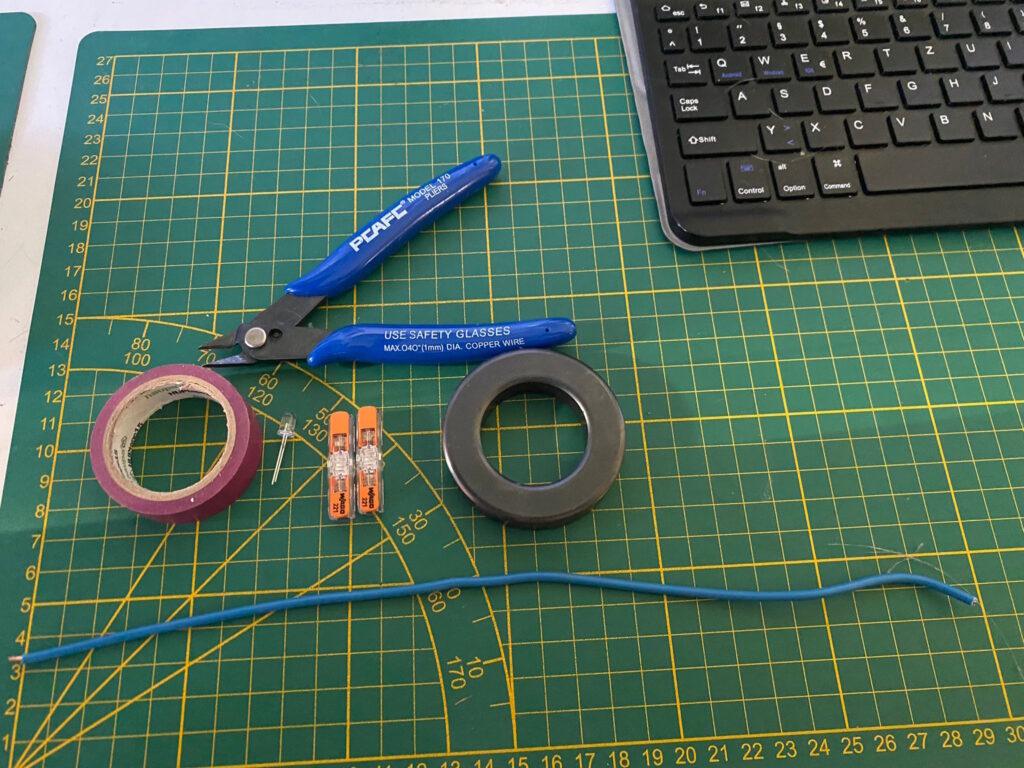
Material required:
- 1x ferrite core (FT 243-43)
- Approx. 30 cm 1.5 mm² electrical wire (longer length is possible, then more turns)
- 2x Wago connectors (can also be soldered directly)
- 1x LED (color of your choice)
- Optional insulating tape to fix the wire turns
Step-by-step instructions
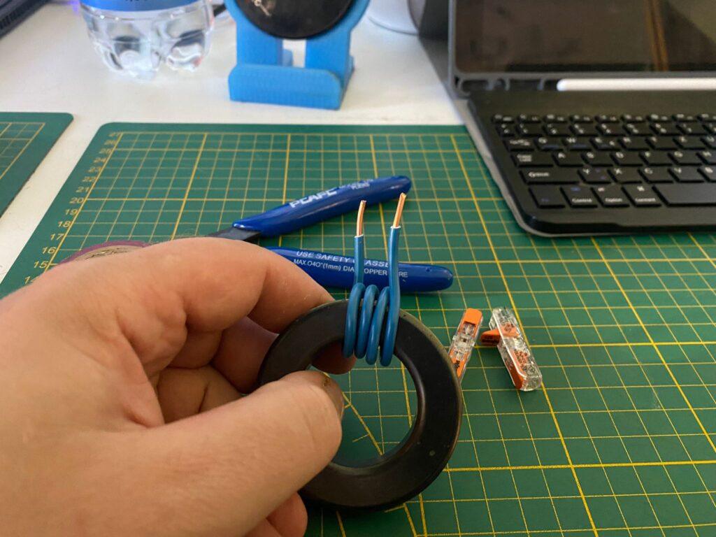
- Strip the wire
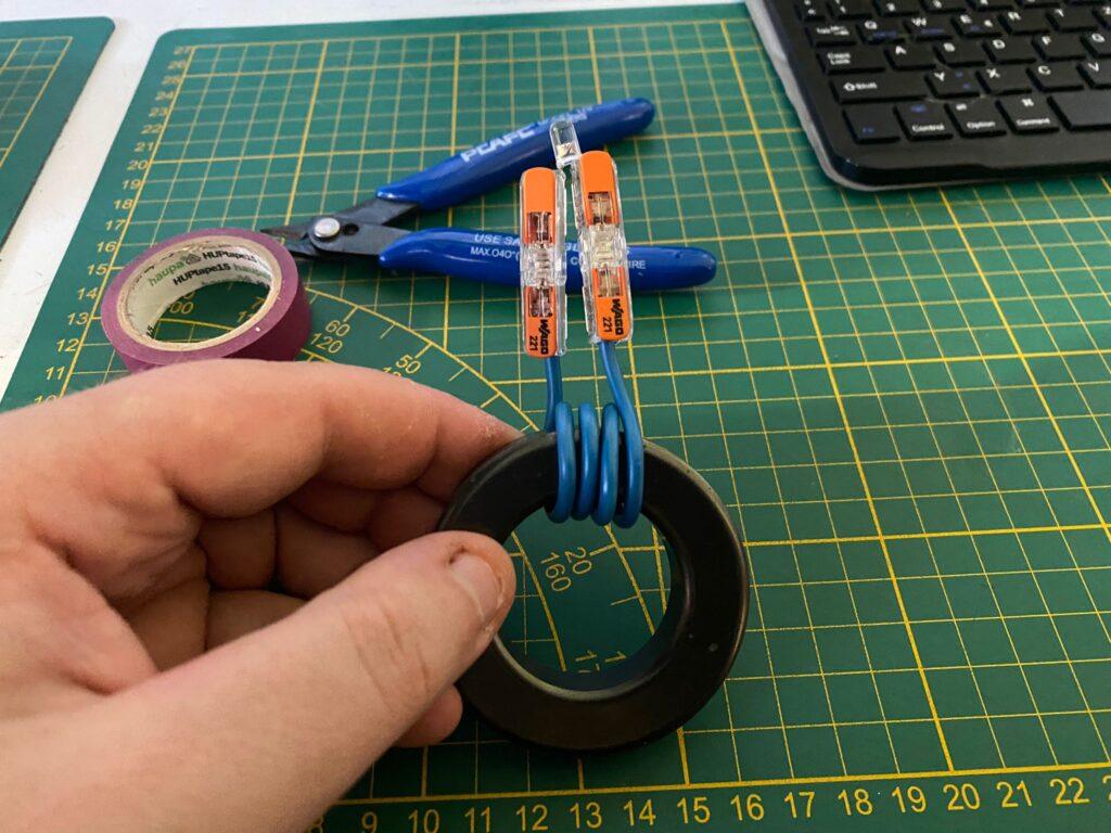
2. Wrap the wire around the ferrite core and align it so that both ends are at the same height above the ferrite core. In this case, about 4 turns fit:
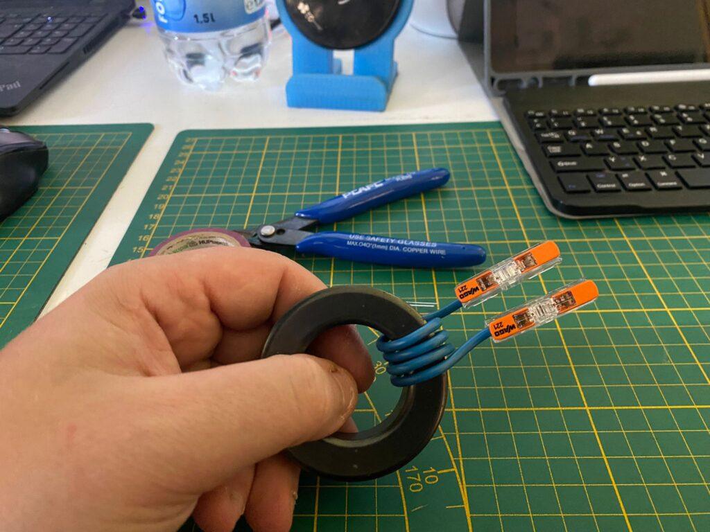
3. Connect the stripped wire ends with the Wago connectors:
4. Bend the legs of the LED so that it fits perfectly into the Wago connectors. Attach LED:
5. Optional step: Secure the coils with insulating tape
Now the coaxial cable to be checked can be pushed through the ring and reconnected to the system. The indicator then shows whether mantle waves are flowing and how strong they are.
If the display is too weak, you can simply wrap a few more turns around the ferrite core to strengthen the display.
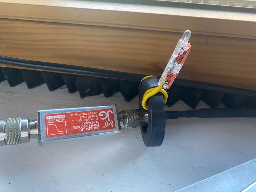
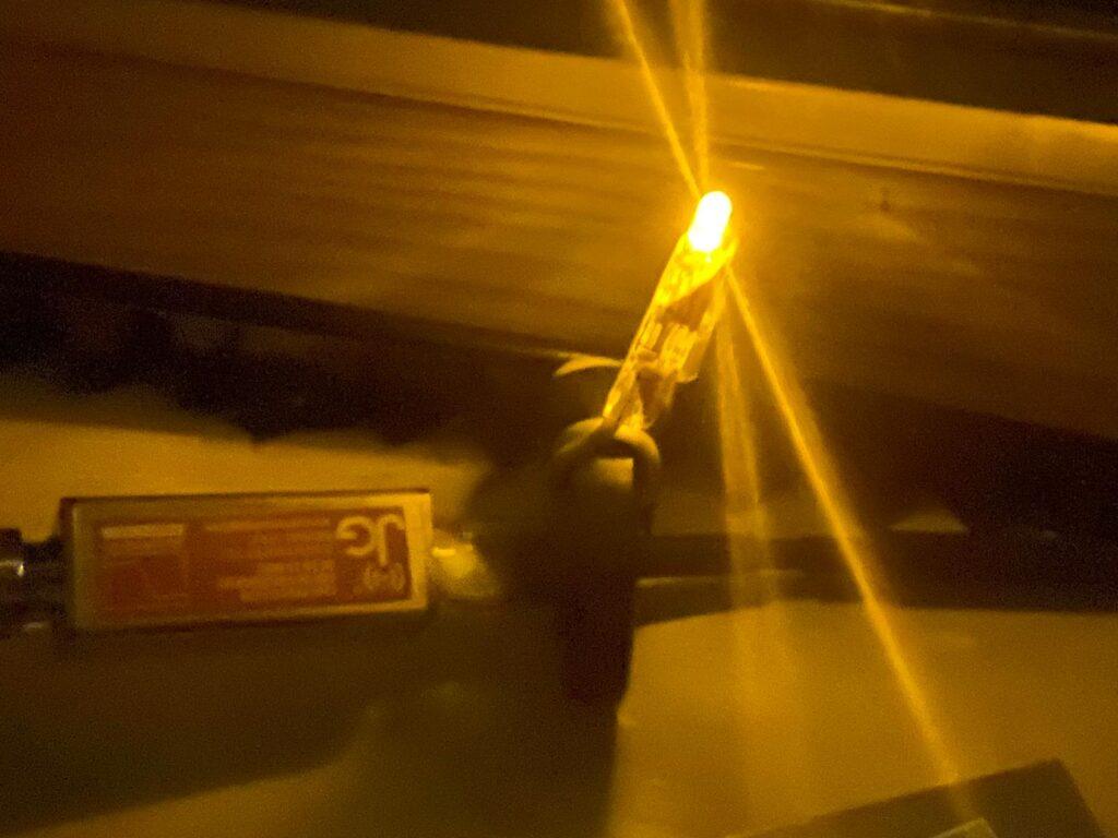
This sheath wave indicator is used by Michael OE8YML on his end-fed random wire antenna at home. There the LED glows beautifully in the dark when it is active on bands over 40 m – ideal for continuous carrier applications such as FT8, as you then have a nice lighting ambience, depending on the LED color selected.